Create Cutouts Using a Sketch or a Wireframe Element
You can create cutouts using a sketch or a wireframe element.
-
From the
Refine section of the
action bar,
click
Cutout
 .
.
-
Click
Standard
 .
.
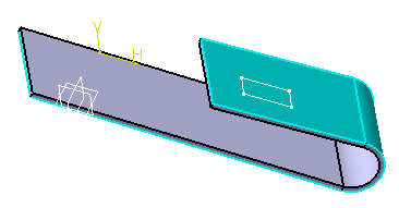
-
In the
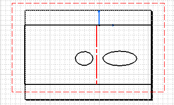
Profile box, select the sketch.
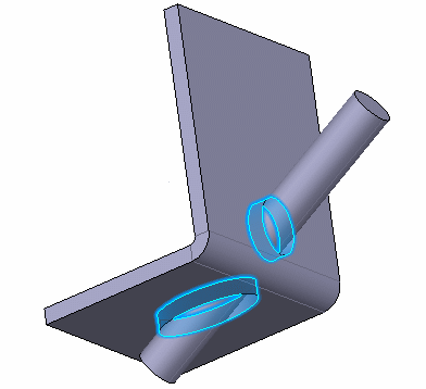
The vectors show the side and the direction of the cutout.
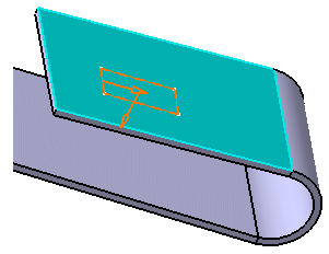
Notes: The following options are available:- Open
catalog
 : Inserts a profile from a catalog.
For more information, see
Browsing
the Sheetmetal Catalog.
-
Normal to profile direction
 : Positions the cutout direction perpendicular to the
selected sketch.
- Reverse
direction
 : Inverts the direction of the extrusion.
-
Reverse material
 : Chooses between removing the material defined
inside the profile, which is the default behavior, and removing the material
surrounding the profile.
- Open
catalog
-
To define the limits, select the type and its associated
parameters:
Option Description Dimension Creates the cutout using a depth value. Up to next Creates the cutout up to the next surface. Up to last Creates the cutout up to the last surface. - Enter a length for each limit.
-
Optional: To manage the impact of the cutout results, select
your options:
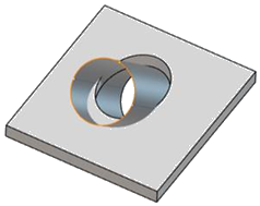
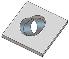
Option Description Optimize Geometry Improves the result of the cutout by taking into consideration impacts on both the top and bottom faces. Note: You cannot use this feature when the cutout result impacts complex geometry (such as propagated flanges, or stamps).Faces Specifies the faces for which you want to manage the impact of the cutout result. Gap Specifies the gap between the input surface and the cutout result, when Optimize Geometry is selected.

