-
From the Weld section of the action bar, click User Swept Weld
 . .
-
Select a weld body in the
tree.
-
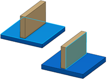
Select the faces you need as supports.
 Note:
To control the faces, you need:
- To add or remove faces defining the supports (as
displayed in the Supports list), press Ctrl + Click.
- You can add to or remove faces from a support
using the Edit
selection
context menu from the Supports list.
- Clicking a face in the work area adds it to the list.
- To remove a face from the list, use
Remove
selection.
- Select the closed profile.
-
Click
Preview.
The user swept weld sections appear and the edges along which they
will be propagated are highlighted.
-
Optional: To generate weld annotations on a drawing, specify a
welding symbol, a weld size, and a weld length in Drafting
Parameters.
-
Optional: To specify a dashed weld, click the Type tab
and select a creation mode. For more information, see Creating a Dashed Weld.
-
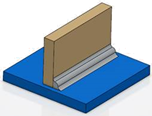
Optional: Select
Generate Weld Impacts.
The app performs a Boolean subtract of the weld shape from the
plates being welded.
-
Click
OK.
The user swept weld is created.
It appears with aggregated supports
and external references in the tree.
- An assembly protected weld preparation is created and appears under the
Assembly features
 node. node.
- The welded 3D shapes are prepared.
|
 appears as a feature in the PartBody including
impacted 3D shapes. A rep impact
appears as a feature in the PartBody including
impacted 3D shapes. A rep impact  is created, maintaining a link between the root
product under which the bundle of weld, weld body, and welds are created.
Rep impact appears under Impacts manager
is created, maintaining a link between the root
product under which the bundle of weld, weld body, and welds are created.
Rep impact appears under Impacts manager
 .
.