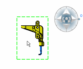
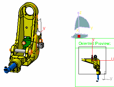
Create a Front View
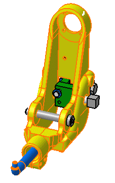
You can create the front view either from a part or from the sub-part of a product, using a reference plane.
- From the View Layout section of the action bar, click Front View
 .
. - To define the reference plane, select either of the following:
- A plane of the 3D part or a plane surface.
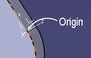
Important: If you select a plane surface, the reference orientation is the external normal of the planar surface. - Two edges: These edges correspond to both axes defining the reference plane according to which the front view is generated. The first edge determines the horizontal axis.
- A point and an edge or vice versa, two points and an edge, or three points: you can thus define a plane.
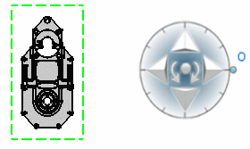
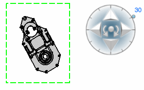
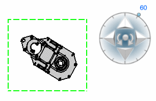
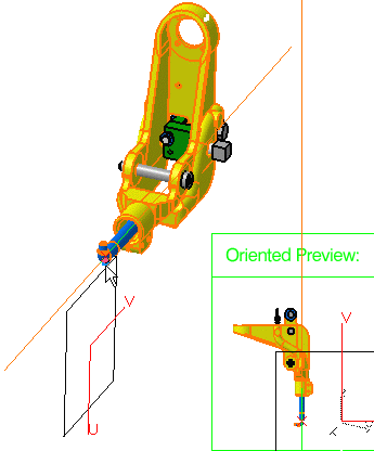
View orientation handle appears that lets you redefine the projection plane before generating the view. For more information, see Define the view orientation during view creation.
- A plane of the 3D part or a plane surface.
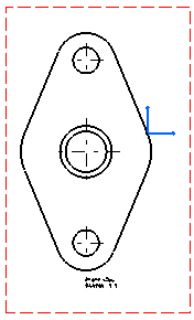
- Click in the drawing to generate the view.

Tip: By default, the axis and centerlines are generated. You can also view hidden lines, threads, fillets, and project 3D points. To configure the view properties, right-click the frame of the view and select Properties. In the Properties dialog box, under the View tab, select the required options.

