About Stacking Layers | ||||||
|
| |||||
A layer stacking has the following attributes:
- Stacking ID: unique identifier for the stacking.
A unique identifier is proposed. You can change the identifier which is verified for its uniqueness.
- Layer stacking: list of layers. You can add only valid Layers to the layers list and edit it.
Concept Structure Engineering verifies the validity of the value and does not allow invalid values. It also shows the corresponding layer Part names in the Stacking panel. For each layer, an icon is created with the sequence of colors.
- Reference ID: index of the base layer in the layers list. No offset operation is performed for the base layer.
You can only insert valid Reference IDs and edit it. Concept Structure Engineering verifies the validity of the value and prevents invalid values.
- Stacking name: user-defined name for the stacking.
- Connection ID: unique identifier for the applied connection.p
The identifier provides a reference to the connection specifications. Concept Structure Engineering additionally shows the corresponding connection name in the stacking panel.
- Used: flag that indicates that the stacking is assigned to surfaces.
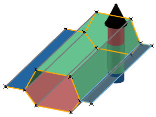
Every stacking has a reference layer that is used as base layer from which the distance calculation starts. The example in the figure illustrates the stacking of layers and the meaning of the reference layer. The distance is calculated from one layer to the next, taking into account the layer thickness. The Mesh command then reads these distances for the mesh generation.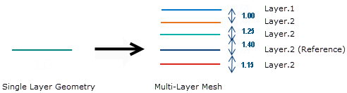
Calculation of Virtual Flange Layers as an Intermediate Step to a Multi-Layer Mesh
To build virtual layers from a single-layer geometry, a list with all layers is defined in the surface. The layer assigned to the first selected surface is the reference layer. It remains at the position of the single layer geometry. From the layer thickness is computed an offset to the other virtual layers. The layer boundaries are translated in a way that intersections in the mesh are largely avoided.
Apply Connections in Stacking Specifications of Multi-Layer Flanges
To generate connections between each layer, a reference to a Connection feature is required. This feature contains the following information:
- connection ID
- connection type
- spot positioning in the flange area
- a template describing which layer is connected at each spot position
The connection ID references a connection specification in a stacking specification.
Layer Stacking Orientation
By default, a layer stacking is oriented in direction of the surface normal to which it is assigned. Vector symbols display the layer stacking orientation.