Create Typical Cross Section
You can create a typical cross section that is an input necessary for the subgrade surface creation.
Before you begin:
The schema below illustrates the railway structure: 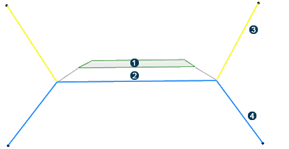
 Subgrade layer 1
 Subgrade layer 2
 Excavation
profile
Excavation
profile
 Filling
profile
Filling
profile
-
To generate excavation and filling surfaces in layer subgrades, you need to
add excavation and filling profiles as outputs of the UDF.
When you define an UDF as a typical cross section, the UDF must have:
- A Base Axis System as input. It can have additional inputs.
Tip: To set a Base Axis System as an input of the UDF, do the following: - click Formula
 from the Tools section of the
action bar.
from the Tools section of the
action bar. - Select Axis System in the New Parameter of type list.
- Click New Parameter of type and Add Formula and, select Axis System. Click Update. The tree is modified accordingly with the f(x) Axis System.
- In the tree, replace the initial axis system with the Formula axis system.
- From the Civil Engineering
section of the action bar, click User Feature Definition
 and select Axis System in the Inputs of
components panel of the User
Feature Definition dialog box.
and select Axis System in the Inputs of
components panel of the User
Feature Definition dialog box.
The Base Axis System is an input of the UDF.
- click Formula
- Exposed parameters that will be retrieved in the Subgrade command.
- Opened or closed curves as outputs.
Excavation and filling profiles are added to the subgrade cross section. - A Base Axis System as input. It can have additional inputs.
-
To type the outputs of the subgrade, type the main result and/or the
outputs of the UDF. For this, do the following:
-
Open the part containing the UDF and click Define
Specification
 from
the Civil Engineering section of the action bar.
from
the Civil Engineering section of the action bar.
- Optional: Select the Subgrade Layer type and one or several UDF outputs (created layers) in the tree.
These types are mapped on the subgrade outputs.Excavation and filling profiles must be typed as excavation and filling to be detected by the Road/Railway Subgrade command. If so, the command switches to an Earthwork context with additional functionalities.
Tip: To check if the output is typed, click BIM Attributes from the Civil Engineering section of the action bar. A typical cross section is created.
-
Open the part containing the UDF and click Define
Specification