Managing the View Modes

You can modify the current view using predefined view modes, or by tuning some parameters. You can also apply default or customizable appearances to your objects.

This task shows you how to:


Before you begin:
  • The View Modes command is available in the action bar only if the V2 (with appearance) option is activated in the preferences. Otherwise, the former user interface is available.
  • When the panel opens, the current shading mode used in the viewer is activated by default. When you click a shading mode, the list of available options with their associated values dynamically updates from top to bottom in the panel. Inversely, if you activate or deactivate some of these options, the corresponding shading mode is activated.

Click Play to watch the video:

Define Shading Options

You can change the default shading.

  1. In the upper part of the View Modes panel, click the appropriate icon to apply the corresponding shading mode.

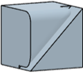
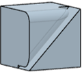
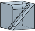
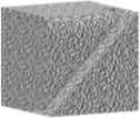
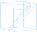
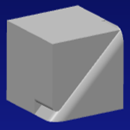
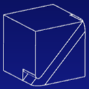
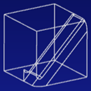
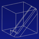
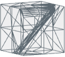
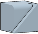
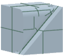
    Shading Shading with sharp edges Shading with sharp edges and half visible smooth edges Shading with sharp and smooth edges Shading with all edges and hidden edges Shading with Materials Wireframe
    Shades the surfaces of the object without edges. Shades the object's surfaces with its edges, except the smooth ones. Shades the object's surfaces with its edges and the half visible smooth ones. Shades the object's surfaces with its edges, whether smooth or not. Shades the object's surfaces with all its edges (sharp and smooth), whether hidden or not. Displays the materials applied onto the object.

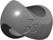
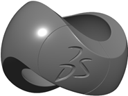
    When no material is applied,Basic for design is used. It is a rough plastic with a shiny coating layer that uses the 3DS PBR material type and takes the model's color as input.

    Uses simple geometry, such as a point, line, or curve to represent the outline of the 3D object.

    For each surface or solid, the colors of all the object's faces are retrieved to look for the dominant color (the most used color). Otherwise, edges are applied the color defined in the Properties dialog box.

    By default, the color is black.

  2. In the Shading area, specify if you want to use the object's shading, or a default one.

    Option Description
    Use object shading Takes into account the rendering styles that have been defined in the Properties dialog box or in the Object Properties panel.

    Usually, these attributes are ignored when drawing objects.

    For more information, see Viewing the Rendering Style per Object.

    Default shading Shaded HRD Wireframe Line on Line
    Shades the surfaces of an object without edges.
    Note: Edges can be displayed through the Edges options.
    Displays the geometry in quick dynamic hidden line removal mode.

    3D faces visually blank out any element located behind them, including 1D elements (such as wireframe elements).

    Displays an object in a mode where only its edges are visible.

    This amounts to clicking Wireframe .

    Lets you visualize superimposed lines by displaying them in a different color.

    Recommendation: Specify a dark color background for a better visibility of the model.

Define Faces Options

You can specify the display for faces, and use appearances.

In the Faces area, specify the display for the faces and the material applied on your objects.

Note: This area is available in Shaded mode only.
Option Description
Faces Lets you specify how faces are displayed by clicking a type in the list.
Fill Triangles

Shades the surfaces of the object.

Displays the triangles on the geometry's faces.

Use object material Lets you use or not the material attached to an object.
Default Appearance Specifies the default material used for all objects.

The list provides three types of appearances.

  • Default appearances
  • Predefined appearances
  • Generic and customizable appearances

Important:
  • This option is available only when Shaded is the default shading mode, and when Fill is clicked in the Faces list.
  • The Iray engine does not support the materials available in the Default Appearance list.
Default appearances
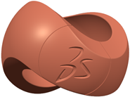
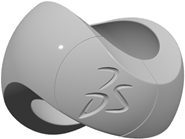
Basic Basic for design Transparent
Predefined appearances - Plaster and Plastic
Clay White mat plaster Grey shiny plastic
Predefined appearances - Aluminum
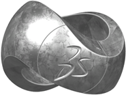
Cast aluminum Machined aluminum
Predefined appearances - Steel
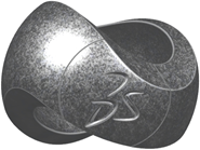
Cast stainless steel Brushed stainless steel Machined stainless steel
Predefined appearances - Red metals
Copper Brass
Generic appearances
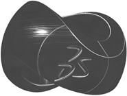
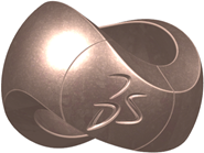
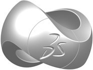
Generic Plastic Generic Metal
When you select a generic appearance, the following additional parameters are available to let you customize the appearance.
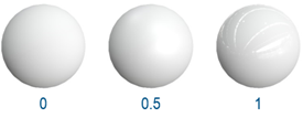
Shininess Controls if the material is rough or shiny. The higher the value, the shinier the material.
Generic Plastic

Generic Metal

Use object color Lets you use the object's color.
Default color Lets you define the color applied to the object. This option is relevant only if Use object color is not activated.
Example with Generic Metal. Customized default color and shininess defined to 0.65

Opacity Controls the transparency of the surface.

An opaque surface has a transparency of 0.0, a transparent surface like glass or water has a transparency of 1.0.

Define Edges Options

You can specify the display for edges.

  1. In the Edges area, specify if and how edges are displayed.

    Option Description
    Edges No edges Only sharp edges Sharp + Half visible smooth edges All edges
    Displays the object without any edge. This mode is used by Shading. Shades the object's surfaces with its edges, except the smooth ones.

    This mode is used by Shading with sharp edges.

    Shades the object's surfaces with its edges. Smooth edges have the same color but with a 0.5 transparency so that they are less visible than sharp edges.

    Edges have the color defined in the part body's graphic properties.

    For objects with multiple colors, the edges have the color of the face they belong to.

    This mode is used by Shading with sharp edges and half visible smooth edges.

    Displays the object with all its edges (smooth and sharp).

    This mode is used by Shading with sharp edges and smooth edges.

  2. If edges are visible, use the additional options that are available..

    Option Description
    Hidden edges Activates or deactivates the display of hidden edges.

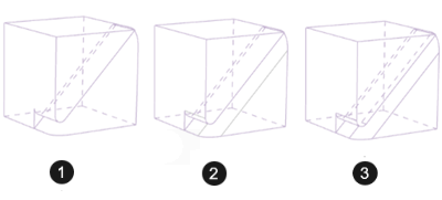
    For example:


    (1) Hidden edges and Only sharp edges

    (2) Hidden edges and Sharp + Half visible smooth edges

    (3) Hidden edges and All edges

    Vertices Activates or deactivates the display of vertices for edges.

    If you activate the option, you can only display and select free points. This enhances the overall readability for complex models and has a positive impact on performance.

    Color from face Colors edges (border edges, internal smooth edges, or sharp edges) according to the color applied to the geometry's faces.

    For internal edges, if the two adjacent faces have a different color each, the edge's color is the color of the face whose bounding sphere's radius is the smallest. The real surface is not taken into account.

    Depending on the underlying feature, there are two possibilities:

    • The bounding sphere is the smallest sphere that includes the face (most current case).
    • The bounding sphere is larger than the smallest surrounding sphere.

    The amount of memory used increases to compute the color for each edge in the object.

    Important: This option is available when the Default shading is Wireframe or Line on Line.

  3. Use the Outline and Isoparametrics options to display or hide the outline and topological elements.

    Option Description
    Outline Specifies whether the outline is visible or not.


    This mode is especially useful when working with surfaces of revolution (such as shafts or cylinders) but there is a price to pay in memory usage when using this mode.

    Isoparametrics Displays or hides topological elements defined as being isoparametrics.


    To use this mode, first select the Enable isoparametrics generation option in the Performance area.

    Important: This option is available when the Default shading is Shaded.

Define View Filters Options

You can use filter options to hide or display elements on your model.

In the View filters area, activate the appropriate options to display or hide points, reference axes and planes, and wire elements.
Points Axes and planes Wires
Important:
  • These options have no impact on V5 FTA features, 2D Layout features (2D or 3D), 3D annotations, sketches in Sketcher, sketch axes for Working on support, and Working on support features.
  • Axes from Sketcher cannot be filtered.

Save your Customization

When satisfied with the result, you can save your customization to keep it for later use.

When finished, click either:

Option Description
Custom view mode

Lets you apply the last saved customized view mode to the current tab and to the tabs you might open afterward.

Save custom view mode

Lets you save your customized view mode. The new customization replaces any customization you might have previously saved.

The first time you run the command, the options for the open tab are activated in the dialog box.