Creating Splice Plies | ||
| ||
- From the Producibility, Flattening and Splicing section of the action bar, click Splice Plies
 .
.
- Select the plies from which you want to create splice plies.
- Multiselection of entities
 is available.
  in the dialog box that appears gives access to the Stacking Management.
- Multiselection of entities
- Select a Curve selection mode.
You cannot select both modes.
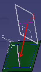
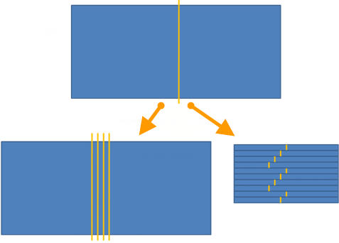
- From 3D allows splicing with curves lying on the ply/plies group surface. The directions are previewed in the work area.
Important: Select the curves in the right order. 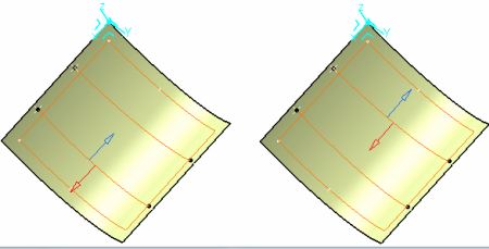
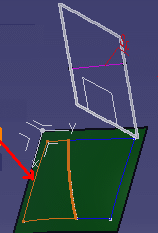
- From 2D allows splicing with curves from the flattened view of the
ply. This provides the best material use and minimizes the cross cutting of fiber on the
cut-piece edge. This is useful for Composites part made using unidirectional material
for thick part (spars).
- With this option, the selected entities must share the same flatten plane. For example, if you select a plies group, the selection is validated only if all the plies inside the plies group share the same flatten plane.
- Once the entity selection is validated, all the plies have the same flatten plane. Only curves lying on that plane can be selected as splicing curves.
- Parallels to selected curves are generated on the flatten plane and Parallel Mode is disabled.
- The input curve is transferred to 3D.
- The new curve on 3D is used to generate the splice plies.
- Geometry transfer from 2D to 3D is based on whether unfold geometry or regular
flattening is done:
- If the plies have regular flattening defined under the flatten body, the options specified in the producibility used for creating the flattening are applied to 2D to 3D Geometry transfer. For example, if the flattening is created using the thickness update option, the same is used for 2D to 3D transfer of selected splicing curve.
- If the plies have unfold defined under the flatten body, options used during unfold creation are used.
- If a thickness update is done:
- A straight line selected in 2D is not a straight line in 3D. But for manufacturing purpose, the flatten view will be correct.
- Due to tessellation during the geometry transfer and flattening operation, when flattening a cut-piece, there may be a deviation between the selected curve for the 2D splicing and the contour edge of the flattened cut-piece.
- From 3D allows splicing with curves lying on the ply/plies group surface. The directions are previewed in the work area.
- Select the Splicing Curves.
- Multiselection of curves is available.
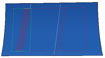
- Intersecting curves are supported. For example, the curves below will result in 6 cut-pieces with valid contours.
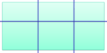
- Multiselection of curves
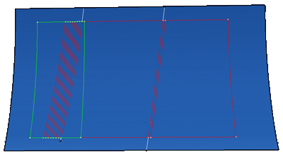
- Optional: Select the Repeat Staggering check box to reuse computed parallels to generate splice plies. Enter a repeat value.If the repeat value is specified as N, the staggering step is reset to 1 after staggering N steps.
In our example below, there are 10 plies. The repeat value is 4.
- Four curves are created.
- Plies 1 to 4 have the staggering steps 1, 2, 3, 4.
- Plies 5 to 8 have the staggering steps 1, 2, 3, 4.
- Plies 9 and 10 have the staggering step 1 and 2 respectively.
-
Optional: Select the Tamp the curves if needed check
box to optimize the shape of the cut-pieces.
All initially generated splicing curves are inspected. Unused curves are removed. The computation formula is updated to create the next curves according to staggering rule and splice plies correctly.
- When Tamp the curves if needed is cleared
- When Tamp the curves if needed is selected
When the check box is selected, when splicing island plies belong to the same sequence, the curves used to create the cut-pieces are not staggered for each plies: the same curves are used for all island plies in the sequence.
- When Tamp the curves if needed is cleared
The 3D Multispice feature is created and includes:
- The selected plies
- The splicing curves
- The staggering value
- A staggering direction per curve
- The overlapping value
- An overlapping direction per curve.
Splice plies (also called cut-pieces) are created under each ply and have the following characteristics:
- They inherit the material and direction of the ply
-
Their contour is
associative with the parent ply geometry in the following cases:
- The ply surface is modified.
- The ply geometry is modified. For example, the boundaries of the plies are modified, or a
limit contour is applied to the ply.Note: The number of cut-pieces is not modified during the update of the part. For example:
- Original situation:
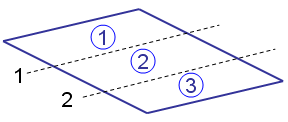
- Situation after update:
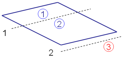
Curve 2 no longer intersects the parent ply geometry. The limit contour feature of cut-piece 3 has an update error. Delete the cut-piece manually.
- Original situation:
- They have their own rosette and producibility feature.
- They have their own geometry and can be modified individually.
- They are taken into account in the following tasks:
- They can be used for any manufacturing export.
- They can be transferred in the manufacturing model if generated in the engineering model.