Start the Producibility for Fiber Placement
You can select the basic input in the Home tab of the dialog
box. The default parameters meet most of the cases.
-
From the Producibility, Flattening and Splicing section of the
action bar, click Producibility for Fiber
Placement
 . .
-
Select the ply to process.
- The ply is highlighted in the 3D area.
- The Home tab is activated.
-
Select the Propagation type.
- ATL Priority Angle
- ATL Priority Steering
- AFP Priority Angle
- AFP Priority Steering
For more information, see Strip Propagation Modes.
-
Select seed points used to start the propagation of the fibers.
-
Select Point selection and pick an existing point that
lies on the surface, within the external contour of the ply.
-
Right-click Point to create the element you need.
-
Select Point indication and pick a point, existing or not
(Pick where you would create a seed point), within the boundaries of the selected
ply. This allows you a quicker analysis of the producibility as you can restart the
analysis with another point without creating an existing point.
-
Define regions or sectors for each tape or tow in the table under
Geometry reference.
-
Select New Sector and select or indicate points as explained
above.
A new sector is created and activated.
-
Optional: Right-click the required element to modify the input.
Depending on the element, you can
- Clear the sector
- Clear the cell
- Insert wireframes
- Insert operations
- Activate or deactivate the element
- Specify a propagation type.
-
When available, select a Fiber Initialization from the list.
-
Define the Warp and Weft values for the
fiber meshes.
Warp is the radius used to simulate the fiber behavior along
the X-axis, Weft is the radius used to simulate the fiber
behavior along the Y-Axis.
Producibility parameters (that is, seed point, warp, and weft) are now stored as
Producibility params.x under each ply, and may be later used when
flattening plies. Existing producibility parameters sets are kept. Right-click producibility
parameters to edit them, or activate them, or mark them as not usable for
manufacturing.
Specify the Material Parameters
You can retrieve information about the material referenced by the ply, and edit
some others.
-
Go to the Material tab.
The following parameters are displayed for information, but cannot be edited.
- Name
- Type
- Material Width
- Warn angle
- Limit angle
-
Edit the other parameters as required.
- Warn Steering
- Limit Steering
Update the Thickness
You can update the thickness.
This method uses the thickness defined for the material, not the effective one.
-
Go to the
Thickness Update tab.
-
Select the With thickness update check box
to activate it.
-
Press the required icon to define the type of computation.
-
Select the elements to process, Full
Stacking or Ply group only.
-
When available, enter the Max Slope value.
Fine-tune the Simulation
You can fine-tune the simulation using the Advanced
Parameters.
Note:
The content of the tab varies with the selected propagation type.
-
Go to the Advanced Parameters tab.
-
Enter the Geometry Parameters values.
-
Select a Deformation Model.
For more information, see Strip Propagation Modes.
-
Enter the Material Parameters values.
Manage the Results
You can control the display of results appropriate to the physics underlying the
solution, and the geometry on which the results are displayed.
Note:
Not every result can be displayed on any geometry. For example, it usually does not make
sense to display the results on a flat pattern geometry.
-
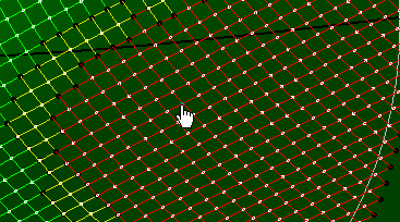
Click Preview to run the simulation.
-
Go to the Results tab.
-
Under Display Result, select the result to display from the
list.
- Shearing Angle
- Deviation.
The content of the list, and other result options depend on the selected propagation
type.
-
For all results, enter the Warning and
Limit values.
Note:
- If those values exist in the material, they are proposed as default values.
- If they do not exist in the material, they are proposed by the selected solver.
- If you edit those values, the modified values are stored in the producibility
parameters.
-
Under Display Geometry, select the required check box.
-
Under Keep Options
-
Click Producibility Inspection to perform one.
See Inspecting the Producibility for more information.
-
Click Keep All Fibers or Keep the selected
fibers to keep all or selected simulated fibers as geometrical curves.
The fibers can be smoothed or projected to be used in subsequent processes, such
as the creation of new contours.
The curves generated by the producibility analysis are kept in a
geometrical set. You can rely on those curves to later create a dart or a splicer
to lower the ply deformation.
Use the inspection points to create limit contours or splice plies curves.
Create Geometry
You can transfer a point or a curve on a ply from 3D to 2D. The 3D point or curve
transferred on the 2D ply must lie on the same shell as the ply, otherwise the transfer cannot
be done. Only the part of the 3D curve lying on the ply is transferred on the 2D geometry.
When the segments exceed the ply contour, they are not taken into account.
-
Go to the Geometry Creation tab.
-
Select the 3D elements (points or curves, including closed curves) to transfer, or
create them from the context menu.
Selected 3D elements are listed under 3D to 2D
transfer, with the category applied to each element.
- By default, the category is No Category.
- You can edit category on each ply.
-
Select 3D elements, sharing the same category or not.
-
Select a new category from the list.
The new category is applied to all selected 3D elements. Note:
If you add 3D
elements with no defined category, the last category you have selected is proposed by
default. You can edit it.
-
Click Remove to remove selected elements from the elements to
transfer.
-
To replace one 3D element:
-
Select the 3D element to replace.
-
Click Replace.
-
Select an element to transfer.
It replaces the selected element unless it is already listed under 3D to
2D transfer.
-
Repeat on all the 3D elements to replace, one by one.
-
Click Preview.
The flattening is previewed on the plane tangent to the ply shell at the seed
point.
-
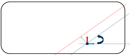
Enter the parameter values to define the Fiber Mesh Curves to
keep.
- Distance: Offset value applied to the rotated curve to
build the result curve (green arrow). It is initialized to half the material roll
width of the ply: When creating cut-pieces using Multi-Add, the seed point is at the
middle of the cut-piece.
- Angle between the warp vector and the result curve
(circular arrow).
-
Click
- Add to create a single curve.
- or Multi-Add: A first curve is created with the entered parameters, as well as
all other possible curves using a distance modified by the material roll width.
The curves are listed under Fiber Mesh Curves.
-
To modify the parameters of a given curve:
-
Select its line corresponding in the list.
-
Modify the distance or the angle and click Modify Values.
-
Click OK.
The producibility parameters are created or updated.
- Fiber Mesh Curves are visible features, updated by their
own build.
- Kept Fiber Mesh Curves are visible datum-like features (no
update).
- 3D to 2D transfers and flatten contours are invisible datum-like features, updated
by producibility build.
|
 : With this option, the surface where the plies are draped
is an offset (by the provided value) of the surface
supporting the plies. The plies ignore all ramps.
: With this option, the surface where the plies are draped
is an offset (by the provided value) of the surface
supporting the plies. The plies ignore all ramps.  : With this option, the surface
where the plies are draped is an exact elevated surface,
computed from the core sample and taking the ramps and drop
off into account. The associated value is the maximum
thickness where plies will be queried by the core sampling
operation.
: With this option, the surface
where the plies are draped is an exact elevated surface,
computed from the core sample and taking the ramps and drop
off into account. The associated value is the maximum
thickness where plies will be queried by the core sampling
operation.  : With this option, the offset value is based on the plies
material thickness.
: With this option, the offset value is based on the plies
material thickness.