Managing Features of Manufactured Parts | ||||||||
|
| |||||||

Click Play to watch the video:
-
From the Authoring section of the action bar, click Edit Features
 .
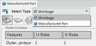
The Manufactured Part panel appears.Note: Selecting a Manufactured Part which shrinkage is planned in Simplified Mode and launching the Edit Features there are 2 items in the field, which are;
.
The Manufactured Part panel appears.Note: Selecting a Manufactured Part which shrinkage is planned in Simplified Mode and launching the Edit Features there are 2 items in the field, which are;- Manufactured Part - You are able to edit manufacturing features.
- Shrinkage - You can edit the shrinkage values of corresponding features of the Simplified Model.
Note: When you select a sub manufactured part with Edit Features, automatically the selected sub manufactured part is replaced by the main manufactured part. After all work preparations complete, run Identical Part Management to update the sub.

In this scenario, after changing the location of the alignment line for either main or sub stiffener from Start to End, the message window appears. This asks to change the location of other alignment lines.

In the Added Material
 and Fit-up
 tabs, you can choose Propagation mode. When creating
margin features for an opening of plate / split plate of panel, this
provides for the margin feature generation at a manufacturing opening
feature. And the feature information extracts to a drawing and XML.
tabs, you can choose Propagation mode. When creating
margin features for an opening of plate / split plate of panel, this
provides for the margin feature generation at a manufacturing opening
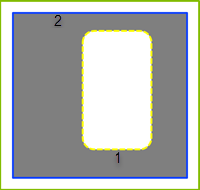
feature. And the feature information extracts to a drawing and XML. - Positive Margin Case - In the
Added Material, on a plate, after selecting the edge of the opening (1), the
positive margin generates.
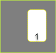
After the Margin feature generation, Mfg opening feature updates by considering the margin value of 10mm (2).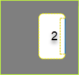
- Negative Margin Case - In the
Fit-up, on a plate, after selecting the edge of the opening (1), the
negative margin (2) of -10mm generates.
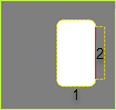
After the Margin feature generation, Mfg opening feature updates by considering the margin value of -10mm.
Propagation mode
This supports a Mfg Marked Opening, Cut Opening and Outer Contour features and the margin feature creation is not supported on a panel.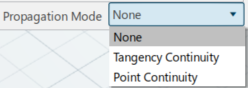
This provides 3 options;
- None -Nothing done.
- Tangency continuity -Expand or collapse the opening feature to the selected boundary’s adjacent edges.
- Point continuity - Expand or collapse the opening feature around all the selected boundary's vertices.
If you want to apply the mode to margin feature to the plate, specify the mode before the margin generation. After margin generation, it is not available to apply propagation mode to the existing feature.
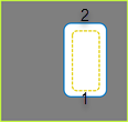
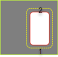
After margin feature generation with propagation mode, the opening and margin feature are generated as shown, left one is Tangency continuity and right one is Point continuity result.

- Tangency continuity - Expand or collapse an opening feature to the selected boundary’s adjacent edges.
- Point continuity - Expand or collapse an opening feature around all the selected boundary's vertices.
-
Target Column
Create margin feature at plate outer contour and Mfg opening feature. And the name of the outer contour or Mfg opening feature at the margin created is displayed under the Target column.

- Open Margin or Bevel Case - Select the
propagation mode, Tangency, or
Point Continuity. The margin or bevel
feature on the plate opening (1) generates (10mm) by applying
the propagation mode.
- The Positive Margin.
- The Negative Margin with a -10.mm (2).
- The Positive Margin.
- Outer Contour Margin or Bevel Case - The
propagation mode can be applied to a margin or bevel feature at
the outer contour, 10mm(2).
After selecting the edge, a margin generates, -10mm (2) with the propagation mode.
- Open Margin or Bevel Case - Select the
propagation mode, Tangency, or
Point Continuity. The margin or bevel
feature on the plate opening (1) generates (10mm) by applying
the propagation mode.
-
In the Manufactured Part panel, select the Burn
side Up
 tab.
If stiffeners are attached to the molded side of the plate, burn side up points in the molded direction.
tab.
If stiffeners are attached to the molded side of the plate, burn side up points in the molded direction. -
In the Manufactured Part panel, select the
Opening Preparation
 tab.
tab.
By default, internal openings are defined to None. If Marked is selected as the Boundary Opening Prep Type, all external openings are created as Marked. If the slots have a mark, there is no change in the outer contour.
-
Click the value in the Opening Type column for a given
opening to change its type. Click
 to
create a new opening with the default parameters, and
to
create a new opening with the default parameters, and  to remove a selected opening.
-
In the Manufactured Part panel, select the
Attachment Line
 tab.
All existing attachment lines list.
tab.
All existing attachment lines list. -
Click the value in the Marked Side or Marking
Side column for a selected attachment line to change its type.
Click
 to swap the current Marked Side value, and
  to swap the current Marking Side value.
-
In the Manufactured Part panel, select the
Alignment Line
 tab.
A list of alignment lines display, showing the Location, Offset, and Length of each.
tab.
A list of alignment lines display, showing the Location, Offset, and Length of each. -
Select an attachment line in the list and click
 to
edit its values.
to
edit its values.
-
In the Manufactured Part panel, select the
Reference Line
 tab.
A list of alignment lines display, showing the Location, Offset, and Length of each.
tab.
A list of alignment lines display, showing the Location, Offset, and Length of each. -
Click planes from the list and click OK.
Selected planes appear in the Reference Planes list. You can click
to delete selected planes, or
to swap the current Marked Side value.
-
Select the Added Material
 tab and click an edge in the auxiliary viewer.
The selection appears in the Added Material table.
tab and click an edge in the auxiliary viewer.
The selection appears in the Added Material table. -
Select the Fit-up
 tab and click an edge in the auxiliary viewer.
The selection appears in the Fit-up table.
tab and click an edge in the auxiliary viewer.
The selection appears in the Fit-up table. -
Select the Edge Preparation
 tab and select Pick Points.
-
Select a row in the table and click Edit
.
The Edit Edge Preparation dialog box appears.Note: In the case of Edge Preparation in Preferences and Edit Features, the names of descriptions for bevel edge preparation types displays. To support customized naming on bevels and prevent a mismatch between product title and power-copy name, the prefix
MfgRsc_inResourceIdentifierremoves this keyword in the delivered files. The keywordResourceIdentifieris used to display edge preparations in Preferences and Edit Features. This name can be different with actual power-copy objects. TheResourceIdentifiername is the name of the power-copy. -
Edit the values for the selected edge preparation and click
OK.
Note: To improve performance, by editing Preferences, this allows you not to generate annotations (FTA) for selective features and parent attachment lines. In the case of the panel, it allows you not to generate attachment line features. Therefore, commands like Update In-Process Models and Edit Features are taking into account these preferences and the total elapse time of the feature generation is decreased.
Except for UserDefined text, all others are dedicated to instantiate annotations for each feature by using Update FTA
 .
.- In Administration mode, open the PPR context for admin in the Heavy Industry Structure Fabrication App.
- Instantiate texts by using UserDefined text under UserDefinedText_PRD physical product.
- This physical product is located as a description in the Annotation chapter with UserDefinedText keyword value. Therefore, your defined texts are instantiated during Update IPM.
The files are in win_b64\startup\EquipmentAndSystems\Manufacturing folder.
- Resource Set - StrMfg_PRM-FTA_V2.3dxml
- Feature Catalog - FeatureCatalog-FTA_V2.3dxml
- PPR Context for Admin mode - PPRContext-Admin-FTA_V2.3dxml
-
In the Edge Preparation
tab, select Propagation mode.
If you want to apply the mode to the bevel feature, specify the mode before bevel generation. After bevel generation, it is not available to apply propagation mode to the existing feature. See Propagation above.
After XML extraction, the Edge preparation node provides under the node of each geometric line of which edge preparation creates under the Opening feature node.

- Case 1 Opening - With None propagation mode,
the opening surface is updated with selected edge of edge
preparation. After XML generation, the Edge preparation node
provides under the line node corresponding to the edge preparation
feature.

- Case 2 Opening - With Tangency or
Point continuity propagation mode, the
opening surface is updated with selected edge and continuities.
After XML generation, the Edge preparation node is then under all
line nodes corresponding to the edge preparation feature.

- Case 1 Opening - With None propagation mode,
the opening surface is updated with selected edge of edge
preparation. After XML generation, the Edge preparation node
provides under the line node corresponding to the edge preparation
feature.


