-
Activate the
Manufacturing Program and click Thread Turning
 in
the Turning Machining Operations action bar. in
the Turning Machining Operations action bar.
A Thread Turning entity is added to the Manufacturing Program. The Thread Turning dialog box appears directly at
the Geometry tab  . .
Note:
Geometry tab includes a sensitive area to help you specify the geometry to be
machined. The part is colored red indicating that this geometry is
required.
-
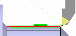
Click the red part area in Geometry tab and select the desired part profile in the work area.
Once selected, the part area changes color to green indicating that this
geometry is now defined.
-
Select the Strategy tab
 to specify
the main machining parameters that are organized in:
Thread, Strategy,
Option, and User Parameters tabs. to specify
the main machining parameters that are organized in:
Thread, Strategy,
Option, and User Parameters tabs.
-
Set the parameters values as shown below in the
Thread tab.
- Depth: 2.5mm
- Pitch: 2.5mm
- Profile: Other
- Orientation: External
- Location: Front
- Thread unit: Pitch
- Threads per inch: 1 (default)
- Number of threads: 25
-
Set other parameters in the
Strategy,Option, and
User Parameters tabs.Geometry Parameters
-
Select the Output CYCLE syntax check box in the
Option tab and in the NC Output
Generation dialog box, to generate CYCLE
statements.
If Output CYCLE syntax check box is not
selected then GOTO statements cannot be generated. You can display and
edit CYCLE syntaxes by clicking the Edit Cycle
command.
-
Go to the Tool tab
 to select a
tool. to select a
tool.
See Assigning a Tool Element to a Machining Operation
-
Select the Feeds and Speeds tab
 to
specify the machining spindle speed for threading. to
specify the machining spindle speed for threading.
-
Select the Macros tab
 to specify the
Machining Operation transition paths (approach and retract motion, for example). to specify the
Machining Operation transition paths (approach and retract motion, for example).
-
Click Simulate or Display to check the validity of the Machining Operation.
See Simulating the Tool Path.
- The tool path is computed.
- A progress indicator is displayed.
- You can cancel the tool path computation at any moment before 100%
completion.
-
Click OK to create the Machining Operation.
|