Creating Manufacturing Fasteners from Fasteners | ||||||
|
| |||||
- Click Manufacturing Fasteners from Fasteners
 .The Create Manufacturing Fasteners From Fasteners dialog box appears. Names are proposed for the manufacturing product and its geometry. Edit them as required. Some sections of the dialog box are collapsed, expand as necessary.
 - Select the design fasteners:
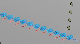
- Select in 3D view a set a points
- Multi-selection with rectangle trap.
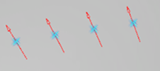
Selection is displayed via arrows. Position and direction are retrieved from design fastener.
Tip: To make a multiple selection of fasteners, press Ctrl or Shift and select the fasteners. - Optional:
From the
context toolbar
that appears, do any of the following:
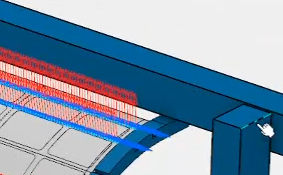
- To select a surface which helps to re-compute and displays the
normal based on the selected surface, click
Select a normal support to set a direction for
MFTs
 .
.
- To invert the axis of all the selected point, click
Reverse the direction of all the selected
position(s)
 .
.
Alternatively, to invert the axis of one point, select the arrow associated with the point.
- To select a surface which helps to re-compute and displays the
normal based on the selected surface, click
Select a normal support to set a direction for
MFTs
- Optional: To position a robot, define the direction of the y-axis identified by a blue arrow:
- Click Set Tangent Direction for All Positions from the context toolbar.
- Select an element of the geometry that has the direction you want the y-axis to be.
 The y-axis of each manufacturing fasteners is updated with the new direction:
Tip: Alternatively, you can modify the direction of the y-axis using Tangent Modification of Manufacturing Fastener from the Manufacturing Pattern dialog box.
- Click Set Tangent Direction for All Positions
- The User Parameters
 is available for deleting or adding parameters when selected in
Me
is available for deleting or adding parameters when selected in
Me  > Preferences > App Preferences > Simulation > Machining
.
> Preferences > App Preferences > Simulation > Machining
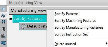
. - Select Manufacturing ViewThe recognized fasteners will be visible using the filter Sort by Machinable Fasteners. When hovering the mouse over machinable fastener then the corresponding machinable fastener is highlighted.
Right-click on a fastener allows you to edit the parameters.