Creating Manufacturing Fasteners from Design Points Position | |||||||
|
| ||||||
 and select the rectangle trap selection mode in the
-
In the
Drilling Riveting section of the
action bar,
click
Manufacturing Fasteners from Position
 .
.
- Optional:
In the
Create Manufacturing Fasteners From Position
dialog box, do any of the following:
- Select a manufacturing product other than the default one.
- Define a rivet reference name in the Reference name list. The parameters of the selected reference appear in the Rivet Parameters area.
- Select a 3D fastener part representation to display. Click
{...} to select a 3D part using the search query, or click
 to select a part referenced in catalog.
-
In the
work area,
do any of the following:
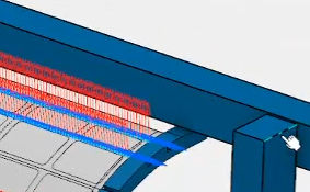
- Select several points using the rectangle trap.
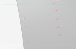
An arrow defining the direction appears at each position. By default, the direction is the z-axis one.
- Select several points created on a line, using the rectangle
trap.
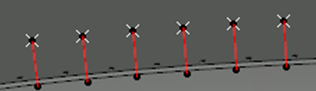
An arrow defining the direction appears at each position. The position direction vector is defined by the selected line.To remove a point from selection, select it again.
- Select several points using the rectangle trap.
-
In the
context toolbar
that appears, do any of the following:
- To set the axis of the arrow normal to a surface, click
Select a normal support to set a direction for
MFTs
 and select one or more surfaces.
Double-click to end the command.
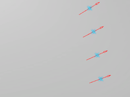
- To invert the axis of all the selected point, click
Reverse the direction of all the selected
position(s)
 .
.
Alternatively, select the arrow associated with the point.
- To set the axis of the arrow normal to a surface, click
Select a normal support to set a direction for
MFTs
- Optional:
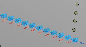
To position a robot, define the direction of the x-axis identified
by a blue arrow:
-
From the
context toolbar,
click
Set Tangent Direction for All Positions
.
-
Select an element of the geometry that has the direction you
want the x-axis to be.
The x-axis of each manufacturing fasteners is updated with the new direction:
Tip: Alternatively, you can modify the direction of the x-axis using Tangent Modification of Manufacturing Fastener from the
Manufacturing Pattern dialog box.
-
From the
context toolbar,
click
Set Tangent Direction for All Positions
- Optional:
Click
User Parameters
 and in the
Edit User Parameters dialog box, do any of the
following:
and in the
Edit User Parameters dialog box, do any of the
following:
- To add a parameter, select a type from the Type list and enter a name and value in the corresponding boxes. Click the button to add the parameter.
- To delete a parameter, right-click a parameter in the Current Data area and select Remove.
Note: This command is available only if the User Parameters check box in Me > Preferences > App Preferences > Simulation > Machining
is selected.
> Preferences > App Preferences > Simulation > Machining
is selected.
-
Right-click in the
Manufacturing View and select
Sort by Manufacturing Fasteners.
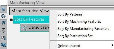
The manufacturing fasteners are displayed. When hovering the mouse over a manufacturing fastener, the corresponding manufacturing fastener is highlighted in the work area.
Note:
To edit a manufacturing fastener, either double-click
the manufacturing fastener or right-click it and select
Edit. You can edit several manufacturing
fasteners by pressing
Ctrl or
Shift before selection.