Insert PP Word in Machining Pattern
You can insert PP Word in Machining Pattern for a single position or for multiple positions in a single shot. You can insert PP Word instructions before any hole in the Machining Pattern. If you use this Machining Pattern in any Axial Machining operation then these PP Word instructions get evaluated and generated in the Aptsource file.
- To edit PP Word for a single hole position.
- Select single hole pattern in the red hole depth representation in the 3DEXPERIENCE platform.
- Right-click on the point manipulator and select Edit PP Word from the point manipulator context menu.
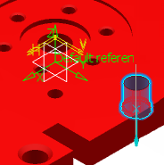
The Edit PP Word for a Position dialog box appears.
Note: If the hole position has some pre-defined PP Words, then the Edit PP Word for a Position dialog box shows that value. If there is no pre-defined value then the Edit PP Word dialog box appears blank. - Edit the PP Word value. Specify the PP Word value, if required.
- Select OK in Edit PP Word for a Position dialog box.The PP Word value, as displayed in the dialog box, gets allocated to that hole/position. If you delete the pre-defined value, then all the PP Word value for that position are deleted.
-
To edit PP Word for multiple hole positions.
The existing PPWords are not displayed while editing PP Word for multiple hole positions as the list of existing PPWords differ from one position to the other within the multi-selection.
-
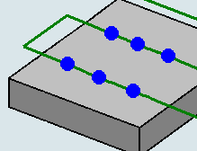
Select multiple holes pattern in the red hole depth representation. Double-click to end your selections.The text No Point is updated with the number of points to machine. In the below image four points are selected.
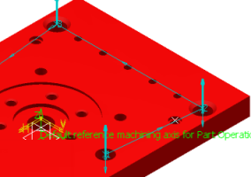
- Right-click the position point in the viewer of Machining Pattern dialog box and select Edit PP Words from the context menu.
Selecting the Define Range to Edit PP Words dialog box appears with the information. - Specify the range of positions for which you wants to insert/Edit PP Words in Define Range to Edit PP Words dialog box.
- Select All, to insert PPWords for all selected positions in a pattern.
- Select the Overwrite existing PPWord values for the specified
positions check box to
overwrite the existing values by the new value
given in Edit PP Word dialog box in all the positions.By default,
By default, this option is not selected.
By default, during editing PP Words for multiple positions, the value given in Edit PP Word dialog box gets appended to the existing PP Word value associated with the positions.
- Select Positions to specify range and exact positions separated by comma in Define Range to Edit PP Words dialog box.
Specific positions is mentioned by the corresponding position numbers separated by commas and range is specified in the format Start position number hyphen (-) End position number : Step.
Here step is a number that you have to add in the Start position number to get the Next position number. Consider a syntax 8-50:10, 8 is the Start position number, 50 is the End position number, and 10 is the Step. To get the Next position number add 10 in the Start position number, so syntax 8-50:10 means that positions considered for Edit PP Word are: 8,18,28,38,48
Some information while specifying range:
By default, step value is 1, so range is specified without specifying step then 1 is considered as the value of the step (for example, 3-6 means 3-6:1 and 3,4,5,6 positions are considered).
When range and step are mentioned in such a way that the end position number is not achievable going by the step then the last position number is not considered and highest position value in the range in considered.
When range is specified beyond the maximum number of positions in the pattern, or specified a position that does not even exist, or a wrong syntax is given then a warning is generated.
- Select Ok in Define Range to Edit PP Words dialog box.
- Specify the PP Word value in Edit PP Word for Multiple Positions dialog box.
- Select OK in the Edit PP Word for Multiple Positions dialog box.The PP Word value is allocated to all the positions. If there is already any PP Word value present and you select Overwrite existing PPWord values for the specified positions check box and does not specify any value in the Edit PP Word dialog box then all the PP Word value for those positions gets deleted.
-
Select multiple holes pattern in the red hole depth representation. Double-click to end your selections.
-
To see the PP Word associated with any single hole of the pattern in the Viewer.
- Right-click point manipulator and select Show/Hide PP Word from the point manipulator context menu.By default,
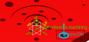
In the above image you can see the PP WordSensor/ON in the viewer.
PP Word is shown in the viewer for all the holes and by the first select of the Show/Hide PP Word in the context menu PP Word gets hidden in the viewer for that particular hole/Position . This happens to the selected hole/position and does not affect the Show/Hide status of other holes/position in the pattern. This option works as a toggle, with one click the PP Word gets hidden and with the next click it re-appears.
The PP word appears in Show state only, whenever you open the Machining Pattern or Axial Machining operation dialog box.
- Right-click point manipulator and select Show/Hide PP Word from the point manipulator context menu.