-
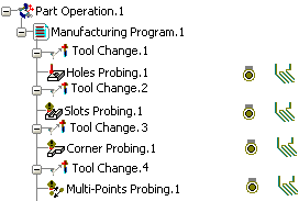
Activate the Manufacturing Program and click Multi-Points Probing
 in the Prismatic Machining action bar. in the Prismatic Machining action bar.
A Multi-Points Probing entity is added to
the Manufacturing Program.
The Multi-Points Probing dialog box opens at the Geometry tab page  .
This tab includes a sensitive icon to
help you specify the
geometry.
Areas of the icon are colored red indicating that this
geometry is required.
-
Still in the Geometry tab:
See Selecting Geometry - Click the red area in the sensitive icon and select the part in the 3DEXPERIENCE platform.
- Double-click anywhere in the 3DEXPERIENCE platform to confirm your selection and redisplay the dialog box.
- Similarly, click Points in the sensitive icon and pick the required locations on a surface. The points are created on the surface using the coordinates of the pointer.
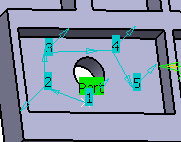
- Those points are listed under the sensitive icon. You can edit
them, remove them, or reorder them.
- The probing direction is the normal to face at the points when you pick and create them on the fly,
- It is the tool axis direction when you select existing points.
- Select the Strategy
tab
 and specify the strategy
and user parameters. and specify the strategy
and user parameters. - Go to the Tool tab
 to select a tool. to select a tool.See Assigning a Tool Element to a Machining Operation - Select the Feeds and Speeds
tab
 and specify the feedrates
and spindle speeds for the operation. and specify the feedrates
and spindle speeds for the operation. - Select theMacro tab
 to specify the desired transition paths.
 -
Click Display or
Simulate to check the validity of the operation.
See Simulating the Tool Path.
- The tool path is computed.
- A progress indicator is displayed.
- You can cancel the tool path computation at any moment before 100% completion.
-
Click OK in the Display or
Simulate dialog box, and again in the main dialog box.
|