-
Activate the Manufacturing Program and click Trochoid Milling
 in the Prismatic Machining action bar. in the Prismatic Machining action bar.A Trochoid Milling entity is added to the Manufacturing Program.
The Trochoid Milling dialog box opens directly at the Geometry tab  . The part bottom and flank in the icon are colored red indicating that this geometry is required for defining the operation. All other geometry is optional. - Still in the Geometry tab.
See Selecting Geometry - Click the red bottom in the icon, then select the desired bottom element in the 3DEXPERIENCE platform.
- Click the red flank in the icon, then select the desired guiding element in the 3DEXPERIENCE platform.
- Right-click Start to set this condition to Out. Click the corresponding relimiting element in the icon, then select the desired start element in the 3DEXPERIENCE platform.
- Right-click Stop to set this condition to Out.. Click the corresponding relimiting element in the icon, then select the desired stop element in the 3DEXPERIENCE platform.
The bottom, guide, and limit elements of the icon are now colored green indicating that this geometry is now defined. These are also indicated on the part. -
Select the Strategy
 tab
to set the Strategy Parameters, and User Parameters. tab
to set the Strategy Parameters, and User Parameters.
- Go to the Tool tab
 to select a tool. to select a tool.See Assigning a Tool Element to a Machining Operation - Select the Feeds and Speeds
tab
 to specify the feedrates and spindle speed parameters for the operation.
 - Select the Macro tab to add approach and retract macros to the operation, if required.
-
Click Display or
Simulate to check the validity of the operation.
See Simulating the Tool Path.
- The tool path is computed.
- A progress indicator is displayed.
- You can cancel the tool path computation at any moment before 100% completion.
- Click OK to create the operation.
The trochoidal motion is generated on the whole tool path while
respecting:
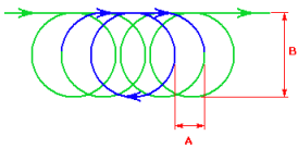
- the Direction of cut (climb or conventional)
- the Engagement (A) of the trochoidal motion, in
particular with the curves
- the Trochoid diameter (B).
|