Synchronizing in an Intermediate Level

You can create reference-reference implement links between assemblies, and then synchronize physical and logical data in an intermediate level.

When you instantiate logical systems in your product structure, assemblies are then handled as references to enable you to synchronize only one assembly in the physical node.

Note: The following scenario describes how to synchronize electrical data in an intermediate level. The scenario is identical for piping data.


Before you begin:
  • In your logical root, create two or more systems containing equipments and logical cables, and instantiate one of the systems (EquipmentSystem1 in our example).
  • In your physical root, insert products and an electrical physical system.
  • Create an implement link between the two roots.
  • In Me > Preferences > App Preferences > 3D Modeling > Electrical and Electronic Systems > Electrical 3D Design, select the Electrical Geometry is mandatory option in the Branch section, and select the Map logical cable to physical conductor option in the Logical to Physical section.
  • Specify the option indicating in which source the content to be placed is searched.

    For more information, see Logical To Physical.

See Also
About Implement Links
Synchronization in an Intermediate Level
  1. Open the logical and physical data:
    1. From the Search Results panel, right-click the logical or the physical root and select Explore With > Explore with System Finder.

      For more information, see System Finder User's Guide: Exploring RFLP Structures.

      Both logical and physical roots are explored in System Finder.
    2. In the tree, select both roots and select Open in the context menu.
    3. Activate the physical root product in Generative Electrical 3D Design.
  2. From the Generative Electrical 3D Design section of the action bar, click Logical to Physical .
    • The Logical to Physical Synchronization Manager dialog box appears.
    • The name of the selected root product appears under Selected Elements.
  3. Select Scan and resolve links, and then click Scan Links.
    Your logical structure appears in the dialog box.
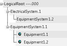
    Note: In the above example, EquipmentSystem1.1 and EquipmentSystem1.2 are instances of the same reference.
  4. Create a reference-reference implement link between two systems.
    1. Under Element, select a logical system (EquipmentSystem1.1 in our example).
    2. Under Compatible elements, select a physical element (EquipmentsRepository.1).
    3. Select Create reference-reference link.


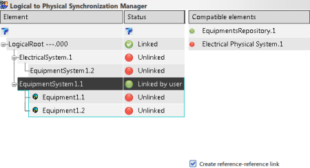
    When EquipmentSystem1.1 is synchronized, EquipmentSystem1.2 will be synchronized as well. Thus, the synchronization in the intermediate level enables the creation of only two equipments instead of four.

    Important: The option is not available if:
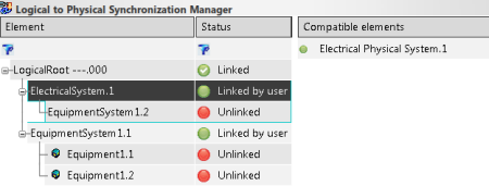
  5. Create contextual implement links between the other elements of your structure.
    In the following example, ElectricalSystem.1 is linked to Electrical Physical System.1.

  6. Click Analyze.
    The status of the physical elements' synchronization appears in the dialog box.
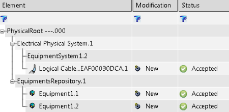
  7. Click Synchronize.
    The synchronization is done in the context of EquipmentSystem1.1:
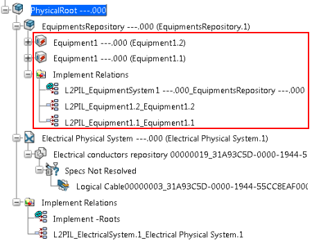
    • In the physical root, a reference-reference implement link is created in the intermediate level. It appears under the Implement Relations node under the physical element you previously selected (EquipmentsRepository.1).
    • Two contextual implement links are created in context of the subassembly.
    • Only two instances (one instance of each equipment belonging to the synchronized logical system) are placed in the physical element.
      Note: In case of synchronization in root context, four instances would be created.


    Note: The implement link created between ElectricalSystem.1 and Electrical Physical System.1 appears under the Implement Relations node in the first level because it was created in the root context.