About Logical
The logical data created in the Functional & Logical Design app is used in the Electrical 3D Design to create the electrical geometry and predefined parts.
In the Functional & Logical Design app, the logical structure and physical structure is created.
The logical structure is created under the Logical node in the RFLP tree structure. For more information about creating logical system, see Functional & Logical Design User's Guide: About Electrical Logical Systems.
The logical structure consists of :
- Equipment
- Connectors
- Busbars
- Harnesses
- Nets (for nets and net groups)
- Conductors (for conductors and cables)
- Ports (for connector ports and pins).
The part number of the physical component from the catalog is defined in the Predefined Part Number box of the logical component.
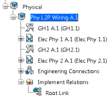
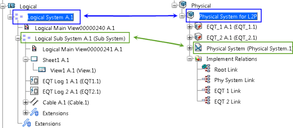
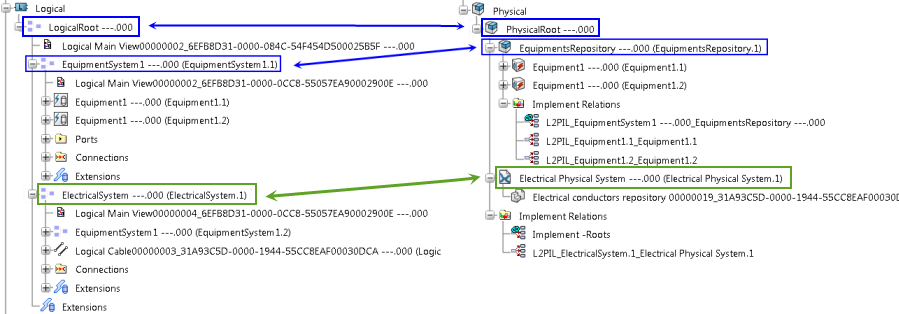
Here is an example of an electrical logical system: 
To create the 3D representation of the logical components, see Systems 3D Allocation User's Guide: Working with 3D Logical Shapes.
The pathways are created in the Systems 3D Allocation app. For more information about creating pathways, see Systems 3D Allocation User's Guide: Creating Pathways.
The electrical harness created in the electrical logical system is routed through the pathway created in the logical 3D world. The electrical harness is routed through the pathway using the Manual Route command in the Systems 3D Allocation app. For more information, see Systems 3D Allocation User's Guide: Routing Manually.