Synchronizing in a Cabling Context

You can synchronize physical data with logical data in cabling networks.

The Logical to Physical command can be customized with business rules.


Before you begin:
  • Create an electrical logical system containing equipment and wires. For more information, see Functional & Logical Design User's Guide: About Electrical Logical Systems.
  • Create the physical structure containing equipment and electrical physical system.
  • Clear the Electrical Geometry is mandatory option in Me > Preferences > App Preferences > 3D Modeling > Electrical and Electronic Systems > Electrical 3D Design > Branch section. Thanks to this option, you do not need to select the electrical physical system when creating the electrical geometry.
  • Create implement links between the Logical root and the Physical root (mandatory before launching the Logical To Physical synchronization). For more information, see Functional & Logical Design User's Guide: Creating Implement Relations.
  • Create implement links between the Logical sub-system (containing equipment, conductors, cables, etc.) and the electrical physical system.
  • Assign the predefined (same) part number to the equipment in the Logical and in the Physical (not mandatory before the Logical To Physical Synchronize command).
  • Use the same name for the Physical cavity and the Logical pin so as to be able to route the cable between the two cavities.
  • If you want to synchronize a logical cable and its route with a physical conductor, select the Map Logical Cable to Physical Conductor option, in Me > Preferences > App Preferences > 3D Modeling > Electrical and Electronic Systems > Electrical 3D Design > Logical to Physical section. See step 6.
  • Specify the option indicating in which source the content to be placed is searched.

    For more information, see Logical To Physical.

See Also
About Logical To Physical
About Logical to Physical Synchronization
About the HTML Report
Available Opening IDs in Logical to Physical Synchronization Resources
  1. Open the logical and physical data:
    1. From the Search Results panel, right-click the logical or the physical root and select Explore With > Explore with System Finder.

      For more information, see System Finder User's Guide: Exploring RFLP Structures.

      Both logical and physical roots are explored in System Finder.
    2. In the tree, select both roots and select Open in the context menu.
    3. Activate the physical root product in Generative Electrical 3D Design.
  2. From the Generative Electrical 3D Design section of the action bar, click Logical to Physical .
    The Logical to Physical Synchronization Manager dialog box appears.
    Tip: You can create missing implement links between Physical and Logical elements during synchronization.
  3. Select the Logical sub-system in the tree.
    The name of the selected element appears in the Logical to Physical Synchronization Manager.
    Note: If you do not create implement links between the Logical and the Physical equipment, you can still check the Scan and resolve links option in the Logical To Physical Synchronization Manager dialog box to find the existing implement links.
  4. Click Analyze.
    Both Physical equipment, with the Unchanged status, are listed in the Logical to Physical Synchronization Manager.
  5. In the Status list, select Accepted or Rejected to determine either to synchronize the element or reject it.

    If the rejected element has some dependencies, a warning appears. Then you can click OK in the message dialog box.

  6. Click Synchronize.
    The accepted elements are synchronized.
    Note: When you select EQT Phy1.1, EQT Phy2.1 or Cable.1.1 in the Logical to Physical Synchronization Manager dialog box, these components and their Logical dependents (and roots) are highlighted in the tree.
    Tip: If you want to synchronize a logical cable and its route with a physical conductor, select the Map Logical Cable to Physical Conductor option, in Me > Preferences > App Preferences > 3D Modeling > Electrical and Electronic Systems > Electrical 3D Design > Logical To Physical section. As a result, the physical conductor with its end devices is mapped with the logical ends of the cable, and its route via branches is mapped with the logical pathways (if defined in the logical system) and linked to the logical cable.
  7. Click Close.
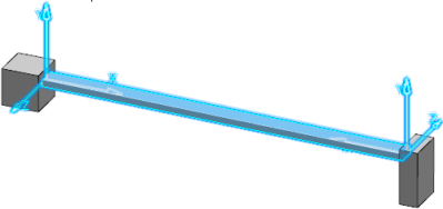
    Cable.1.1 has been created under the electrical physical system but it is not routed through the electrical branch.
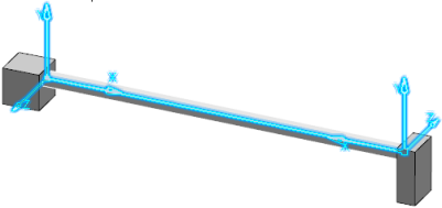
  8. From the standard area of the action bar, click Network Assistant to check the connectivity of the electrical geometry.
  9. From the Conductors section of the action bar, click Automatic Routing and select the Physical cable.
    The Conductor and Conductor Group Routing dialog box appears. For more information about routing, see Routing Conductors Automatically.
  10. Click Close when done.
    The cable is routed through the branch.