Route with Points, Devices and Supports
You can route branches between points, electrical devices, through supports as well as along existing curves and surfaces.
-
Double-click the electrical geometry in the tree to activate it.
- Create the first branch and define branch parameters.
-
Click Route Definition.
The Route Definition dialog box appears.
-
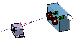
Select a first device in the work area.
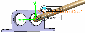
Moving the pointer over a device displays segment connection points or cavity. You can select:
- A device. CATIA finds the segment connection point or cavity closest to your point of selection.
- Published points of the device other than the segment connection point or cavity. Moreover, there will be no link between the segment extremity and the device, and the connection should be made using the Connect Segments command or selecting the segment connection point / cavity.
- A label.
A red arrow appears in the work area showing the direction of tangency. If necessary, click the arrow to reverse this direction.
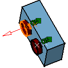
Important: Only the first and last route points can be connected to another branch or a device. -
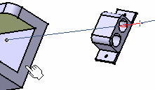
Select a support.
Moving the pointer over a support displays annotations showing the possible entry points of a support.
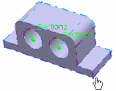
You can select:
-
A support.
If you select a multi-section support instead of a label, the section closest to your selection point is selected.
- A label.

If necessary, adjust the direction and position of the branch going through the support.
-
A support.
-
Select other desired points, devices and supports. The corresponding names are listed in the Route Definition dialog box.
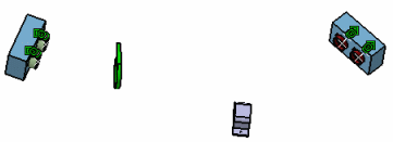
The final branch looks something like this:

- If you want to route your branch in the support more than once, right-click an object and select Repeat Support in Branch Route > Section 1 or Section 2.
In our case, two sections are represented but if your support only contains one hole, then you do not need to choose a section.
- Select the object once again.
You can see a preview of your branches.
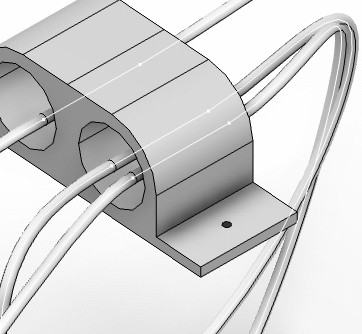
- Click OK to validate.The Route Definition dialog box closes and the Branch Definition dialog box is displayed again.
- Click OK to validate the branch definition.
- Optional: If you want to arrange your segments, select your product and click Arrange Segments
 in the Electrical 3D Design app or click Position in the Route Definition dialog box.
