- From the Protection section of the action bar, click Protective Covering
 .
.
The Instantiate Protective Covering dialog box appears.
- Under Selection mode, select From scratch.
Note:
By default, this mode is selected.
- In the Type list, select one of the following types:
- Fixed Diameter
- Adaptive Diameter
- Corrugated tube
- Tape.
- In the Thickness box, type a value or use the arrows to change the value.
- Click More >> to set other parameters.
According to the selected covering type, parameters are displayed:
- Under Placement mode, select Center.
- In the Length box, type a value or use the arrows to change the value.
- To place a protective covering:
- In the work area, move your pointer over a segment to display each end of the segment.
A blue square appears. It represents the reference point from which
a protective covering is placed.
- Click the segment to select a reference point.
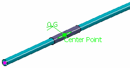
The protective covering is placed over the selected segment. A label indicates the center point of the protective covering.

- To modify the position of the protective covering, do one of the following:
- Drag the Center Point label along the
center curve.
- Double-click the Center Point label
and, in the Edit Center Point dialog box, type a value in the
Distance box, and then click OK.
- Double-click the distance label and, in the Parameter Definition dialog box, type a value in the Value box, and then click OK.
- Click OK to validate.
A new protective covering is inserted and appears under the Protection Set node in the tree.