- Double-click the diagram view.
-
From the Edition section of the action bar, click Create New Reference
 . .
-
In the tree or in the diagram view, select the logical reference (Harness Network).
The
New Content
dialog box appears.
- Expand the Electrical Logical tab and right-click Logical Harness.
-
Optional: Select the
Set attributes at creation option.
Note:
This option remains selected when creating the same type
of component.
-
Click Logical Harness.
The Logical Harness dialog box appears.
-
Type a name (H1) and click OK to create the harness and close the Logical Harness dialog box.
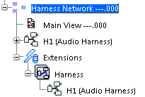
In the tree, under the parent component ( Harness Network), note that: - a H1 (Audio Harness) node is created and aggregates an Extensions node,
- an Extensions node is created under the logical reference (Harness Network). This node will store all electrical objects you will create further. In our example, it aggregates a Harness node containing the extended electrical Harness (H1 (Audio Harness)).
 The symbol defined in Data Setup appears and follows your pointer. -
Click the diagram view at the convenient place to insert the symbol.
The symbol is placed and a context toolbar appears.
-
Click the diagram view to validate the creation.
The symbol is inserted in the diagram view. Notes:
- If another component is already placed, the harness symbol is not connected to the other symbol when placed in view.
- If you place the harness symbol on a route, the route will not split.
- No automatic link is performed when placing an harness symbol on a component or a route.
|