Creation of a Geometric Element
You can create a geometric element by selecting other
elements as inputs.
When creating a geometric element, you often need to select other
elements as inputs. When selecting a sketch as the input element, some
restrictions apply, depending on the feature you are creating.
- You should avoid selecting self-intersecting sketches as well
as sketches containing heterogeneous elements such as a curve and a point
for example.
- However, the following elements accept sketches containing non-connected
elements (that is, presenting gaps between two consecutive elements) as
inputs, provided they are of the same type (homogeneous, i.e. two curves
or two points):
Geometric Modeler Tolerances
The geometric modeler works with a set of two tolerances:
Point tolerance
Two objects closer than the point tolerance are considered as equal.
The point tolerance value is 0.001mm.
Example 1: It is impossible to create a line between two points whose distance is
less than the point tolerance.
Example 2: A curve whose distance from a surface is less than the point tolerance
can be laid down on this surface (to create a parallel curve for instance).
Angular tolerance
An edge with a sharpness smaller than the angular tolerance is
considered as smooth. The angular tolerance value is 0.5 degree.
Example 1: A shell composed of two faces whose angle along their common edge
varies from 0.6 to 1 degree is not considered as smooth. This surface has a
sharp edge which can be made smooth by using the Edge Fillet capability.
Example 2: A shell composed of two faces whose angle along their
common edge varies from 0.3 to 0.6 degree is not considered as smooth.
Manage Colors
You can control the color of 3D shape by selecting appropriate option.
The options are available in
> 2D 3D View Display
> Visualization
> Visualization
> Colors section.
Stacked Commands
You can stack
commands, that is create another basic object in the current command
without leaving it.
All Generative Shape Design commands can be stacked.
Before you begin:
Create a 3D shape containing a point and an axis system. Consider an example with the line functionality.
-
Click Line
 . . The Line Definition dialog box appears.
-
In the Line Type list, select the desired line type. Here we selected the Point-Point line type: two points
are required to create the line. As no point already exists, you will have to create them.
-
Right-click the Point 1 box.
-
Select Insert Wireframe >
Create Point.
Creation commands are now gathered in submenus. Other default commands, such as Center
Graph, are kept at first level. The same organization is
available when right-clicking in the work area.
The Point Definition dialog box appears, as well as the Running
Commands window that shows you the history of commands you have run.
This informative window is particularly useful when many commands
have already been used and stacked, in complex scenarios for
instance.
-
Use the combo to choose the desired point type and select
the On surface type.
-
Choose the xy plane as the Surface.
-
Right-click the Direction box and select the
X Component contextual item.
You can select the Edit Components contextual item
to edit the component's directions (X, Y or Z).
-
Select 50mm as the Distance.
-
Click OK.
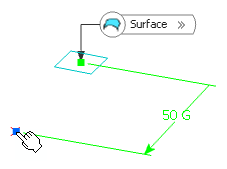
The Point Definition dialog box closes and you return to the
Line
Definition dialog box. The Point 1 box is valuated with the point you have just
created.
-
Right-click the Point 2 box.
-
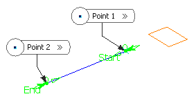
Repeat steps 5 to 9 (select 150mm as the Distance). The Point Definition dialog box closes and you return to the Line
Definition dialog box. The Point 2 box is valuated with the point you have just
created and a line is previewed between Point 1 and Point 2.
-
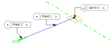
Right-click the Up-to 1 box and select the Y Axis
contextual item. An infinite datum line corresponding to the Y Axis of the Robot
direction will be created.
-
Click OK to create the line. Features created using stacked commands are
aggregated under the parent command that created them and put in No Show in the tree.
If you change
Point.1 by another point (Point.3 for instance), Point.1 is no longer aggregated under
Line.1 and goes one level up.
Even if it is now considered as unused, Point.1 has not
been removed. If you edit the line, you can right-click in any
editable box and select the Delete
Unused Contextual Features item: checking this command automatically
removes all contextual features that are no longer pointed by other
features. As a result, Point.1 has been deleted.
Sub-MenusAll stacked
commands are organized in sub-menus:
- In the first level, you can find the main
categories as well as generic
commands such as Center Graph, Reframe On,
Remove, Replace, etc.
- In the second level, you can find the creation
command items.
Here is the context menu in case of a
contextual feature creation.
The sub-menus for contexual feature edition are avaliable when you right-click in the work area.
Miscellaneous
- For certain commands (like in
the Spline or Fill command), the
context menu changes depending on the selected column, the
feature type (point, line, etc.) and the mode (creation or
edition).
- You can edit the created line and access generic contextual
commands: For Center Graph and Reframe On,
refer to the Part Design User's Guide. For
Hide/Show, refer to Hiding Objects, for
Properties, refer to Displaying and Editing
Graphic Properties, and for Other Selection, refer
to Selecting Using the Other Selection... Command. All these
chapters can be found in the 3DEXPERIENCE
Native Apps User's
Guide.
- In case of stacked commands that do
not have a dialog box (Create MidPoint, Create
EndPoint, Create Extract (in point),
Create Extract (in tangency), etc.), if you want to
return to the stacking command, you need to select the Undo
command.
- The children that appear under
any feature may not follow the same order as their order of
creation.
- Stacked commands are created
using the
Keeping the Initial Element mode, therefore they
do not absorb their inputs.
3D Immersive Flags
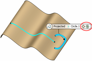
This capability displays immersive flags in the work area to identify the features used as inputs in the dialog box and give the possibility to remove or replace them whenever possible from the dialog box or context menu.
It is available with all commands that use selectors, multi-selectors and multi-lists.
Consider an example with the Line and Projection commands.
- Click Line
 . .The Line Definition dialog box appears. - Select the Point-Point type.
- Select the two points and the support.
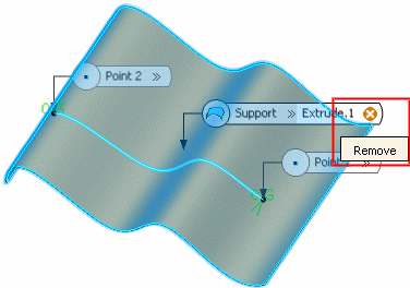
The Support box is optional, therefore it can be freely cleared and reselected through the Clear Selection contextual item. This capability is also available from the Remove icon contained in the 3D flag:
- Click OK in the Line Definition dialog box.
- Click Projection
 . .The Projection Definition dialog box appears. - Select the support, the previously created line and a second feature as the elements to be projected.
The bag icon opens a dialog box that displays selected elements as well as Remove and Replace buttons. These capabilities are also available from the Remove and Replace icons contained in the 3D flag:
- Click OK in the Projection Definition dialog box.
|


