-
Preselect a target or source surface of a matching.
-
Alt + middle-click on the preselected surface and select Modify Control Points
 in the mouse menu. in the mouse menu.
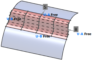
 The Control Points panel opens and control points and continuities at the surface edges are displayed. -
Click Insert/Delete
 and select a position on a control point row. and select a position on a control point row.
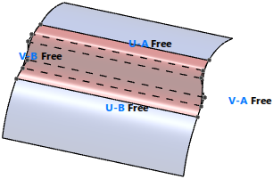
A control point row in cross direction of the selected row is inserted at the selected position.
-
Click again Insert/Delete
and select the edge control point of a control point row.
The control point row is deleted.
-
In the Order section of the Control Points panel, change an order value in the U or V dialog box or by moving the slider.
- Optional:
Click Orders
 and change the orders using the order labels in the work area. and change the orders using the order labels in the work area.
-
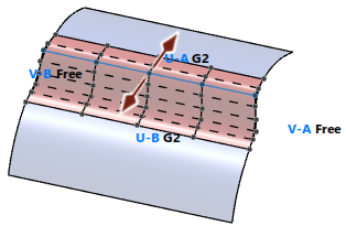
Do one of the following to change the continuity:
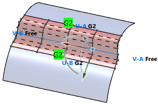
- In the Continuity section of the Control Points panel, select another continuity for side A or B in U or V direction of the selected surface, for example from Free to G2 at the common edges of a blend surface and its input elements.
- In the work area, click a continuity label to select another continuity.
-
Select the second control point row at side A or B.
 The handle indicates that you can modify the control point row in two directions only to keep the continuity when modifying it. -
Select the third control point row at side A or B.
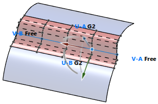 The Robot indicates that you can modify the control point row in all directions without breaking the continuity when modifying it. -
Click
 to display in the work area the condition state at the transition between selected surface and input elements. to display in the work area the condition state at the transition between selected surface and input elements.
Note:
This display is only available for IDX features created with a Soft Parametric Update Mode from Alert and higher.
|