Creating a Geometrical Tolerance | ||||||
|
| |||||
- From the Annotation section of the action bar, click Geometric Tolerance
 .
. - Select an element (geometry, dimension, dimension value,
text or point) or click in the sheet to position the anchor point
of the geometrical tolerance.
-
If you select an element, the anchor point is an arrow.
Note: You can modify this symbol by handling annotation leaders.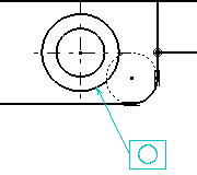
-
If you select the empty space in the drawing, the default anchor point is a filled circle.

-
If you select a dimension, the anchor point is at the intersection of the dimension line and the extension line.
-
If you press Shift and select the extension line, the leader is perpendicular to the extension line and the anchor point corresponds to the position of the pointer when you click to create the geometrical tolerance.
-
If you select a dimension value or a text, no leader is created. The geometric tolerance is displayed just below and parallel to the element you selected.
-
- Click at the required location to position the geometrical tolerance.
For more information about this dialog box, see About Creating a Geometrical Tolerance.Tip: Alt + click in the sheet to position the tolerance vertically. Notes:- At this step, you can apply the parameter values of an existing geometric tolerance to the tolerance you are creating: to do this, select the existing geometric tolerance.
- If you have selected the Use style values to create new objects check
box in
Me
 > Preferences > App Preferences > 3D Modeling > Mechanical Systems
expander, the Geometrical Tolerance
dialog box is automatically completed with custom style values (as defined
in the Standards Editor). In this case, properties in the Object
Properties panel and the Tools
Palette are not available during the creation of the
geometrical tolerance.
> Preferences > App Preferences > 3D Modeling > Mechanical Systems
expander, the Geometrical Tolerance
dialog box is automatically completed with custom style values (as defined
in the Standards Editor). In this case, properties in the Object
Properties panel and the Tools
Palette are not available during the creation of the
geometrical tolerance. If you have not selected this option, the Geometrical Tolerance dialog box is automatically completed with the last entered values (if any). In this case, properties in the Object Properties panel and the Tools Palette are active during the creation of the geometrical tolerance.
- You can reset the current style values in the Geometrical Tolerance dialog box at any time by clicking Reset.
- Click OK.The geometrical tolerance is created.
- To add an all-around symbol to the leader, select the geometrical tolerance, right-click the yellow handle
on the arrow, and then select Application Zone > Global All Around.