Dimension and Annotation Parameters
| Parameter | Value | Description |
|---|---|---|
| International standard | [ISO/ANSI-ASME/JIS] | Each user-defined standard is based on one of 3 international standards: ISO, ANSI-ASME, JIS. This specifies some basic parameters. |
| Dimension Line: Extension on radius dimensions (value inside circle), Reach center | [Yes/No]
|
|
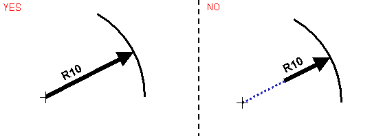
| Dimension Line: Extension on radius dimensions (value outside circle), Reach center | [Yes/No]
|
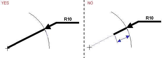
|
| Dimension Line: Extension on radius dimensions (value outside circle), Overrun length | (mm) | |
| Dimension Line: Extension on one-symbol diameter dimensions (value inside circle), Reach center | [Yes/No]
|
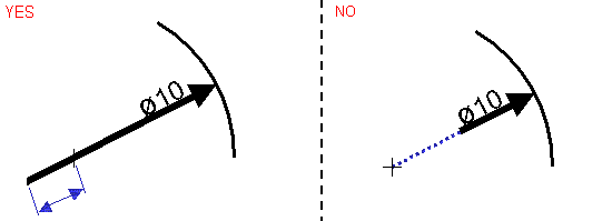
|
| Dimension Line: Extension on one-symbol diameter dimensions (value inside circle), Overrun length | (mm) | |
| Dimension Line: Extension on one-symbol diameter dimensions (value outside circle), Reach center | [Yes/No]
|
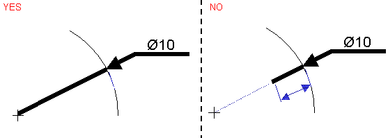
|
| Dimension Line: Extension on one-symbol diameter dimensions (value outside circle), Overrun length | (mm) | |
| Dimension Line: Display and extent (for non-flipped symbols), Overrun length | (mm) |
|
| Dimension Line: Display and extent (for non-flipped symbols), Show | [Yes/No]
|
|
| Dimension Line: Display and extent (for flipped symbols), Overrun length | (mm) |
|
| Dimension Line: Display and extent (for flipped symbols), Show | [Yes/No]
|
|
| Dimension Line: Length for one-symbol dimensions (distance and angle), Underline | [2/1]
|
The dimension line may either have a given length, or automatically adjust to reach the dimension value. |
| Dimension Line: Length for one-symbol dimensions (distance and angle), Constant length | (mm)
Note:
Only positive values are relevant.
|
If Dimension Line: Length for one-symbol
dimensions (distance and angle), Underline = 1, specifies the
constant length of the underlining. If Dimension Line: Length for
one-symbol dimensions (distance and angle), Underline = 2,
specifies the minimum length of the underlining. |
| Dimension Line: Gap around unframed value | (mm) |
|
| Dimension Line: Gap around framed value | (mm) |
|
| DIMTYPos | - | Deprecated |
| Dimension Value: Vertical justification | [2/3]
ISO and JIS only |
|
| Dimension tolerance: Multi-tolerance with associative numerical value | [No/Yes]
|
Specifies whether the numerical definition of a multi-tolerance is associative to the dimension value (in which case it is automatically updated when the dimension value is changed). |
Dimension and Annotation Leader Symbols
| Important: Note that dimension and annotation leader symbols do not apply to arrows. If you want to modify the symbol parameters for arrows, see the Dress-Up Parameters section. |
| Parameter | Value | Description |
|---|---|---|
| Dimension and Annotation Leader Symbols: Open arrow size | (mm) |
|
| Dimension and Annotation Leader Symbols: Open arrow angle | (degrees) |
|
| Dimension and Annotation Leader Symbols: Outlined arrow size | (mm) |
|
| Dimension and Annotation Leader Symbols: Outlined arrow angle | (degrees) |
|
| Dimension and Annotation Leader Symbols: Filled arrow size | (mm) |
|
| Dimension and Annotation Leader Symbols: Filled arrow angle | (degrees) |
|
| Dimension and Annotation Leader Symbols: Transparent arrow size | (mm) |
|
| Dimension and Annotation Leader Symbols: Transparent arrow angle | (degrees) |
|
| Dimension and Annotation Leader Symbols: Slash size | (mm) |
|
| Dimension and Annotation Leader Symbols: Outlined circle size | (mm) |
|
| Dimension and Annotation Leader Symbols: Filled circle size | (mm) |
|
| Dimension and Annotation Leader Symbols: Transparent circle size | (mm) |
|
| Dimension and Annotation Leader Symbols: Crossed circle size | (mm) |
|
| Dimension and Annotation Leader Symbols: Outlined triangle size | (mm) |
|
| Dimension and Annotation Leader Symbols: Filled triangle size | (mm) |
|
| Dimension and Annotation Leader Symbols: Plus size | (mm) |
|
| Dimension and Annotation Leader Symbols: Cross size | (mm) |
|
| Dimension and Annotation Leader Symbols: Symbol reversal limit | (mm) |
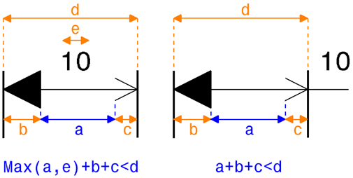 Specifies when the symbol must be reversed:
|
Dimension Value
| Parameter | Value | Description |
|---|---|---|
| Dimension Value: Underlining size, Left tail | (mm) |
|
| Dimension Value: Underlining size, Right tail | ||
| Dimension Value: Underlining size, Vertical space |
Chamfer Dimension Parameters
| Parameter | Value | Description |
|---|---|---|
| Chamfer Dimension: Separator font height | (mm) |
|
| Chamfer Dimension: Value framing | [1/2]
|
|
Half-Dimensions
| Parameter | Value | Description |
|---|---|---|
| Half-Dimension: Dimension line extent (with value inside), Overrun mode | [1/2/3]
|
|
| Half-Dimension: Dimension line extent (with value inside), Overrun length | (mm) | if Half-Dimension: Dimension line extent (with value inside), Overrun mode = 3 |
Dimension Associated Texts
| Parameter | Value | Description |
|---|---|---|
| Dimension Associated Texts: Reference for positioning Before text |
|
reference for positioning 
for Before/After/Insert texts 
for Upper/Lower texts  |
| Dimension Associated Texts: Reference for positioning After text |
|
|
| Dimension Associated Texts: Reference for positioning Insert text |
|
|
| Dimension Associated Texts: Reference for positioning Upper text |
|
|
| Dimension Associated Texts: Reference for positioning Lower text |
|
|
| Dimension Associated Texts: Horizontal offset of Before text | (mm) | |
| Dimension Associated Texts: Vertical offset of Before text | ||
| Dimension Associated Texts: Horizontal offset of After text | ||
| Dimension Associated Texts: Vertical offset of After text | ||
| Dimension Associated Texts: Horizontal offset of Insert text | ||
| Dimension Associated Texts: Vertical offset of Insert text | ||
| Dimension Associated Texts: Horizontal offset of Upper text | ||
| Dimension Associated Texts: Vertical offset of Upper text | ||
| Dimension Associated Texts: Horizontal offset of Lower text | ||
| Dimension Associated Texts: Vertical offset of Lower text |
The following attributes of insert text are available only for legacy compatibility of the V4 dimensions imported into CATIA V5 and 3DEXPERIENCE. You cannot create or add them now:
- Dimension Associated Texts: Reference for positioning Insert text
- Dimension Associated Texts: Horizontal offset of Insert text
- Dimension Associated Texts: Vertical offset of Insert text
Annotations
| Parameter | Value | Description |
|---|---|---|
| Annotation: Text angle | [No/Yes]
|
|
| Annotation: Text leader size, Leader side | (mm) | Warning: This parameter is used only
for roughness symbols created before V5R12.  |
| Annotation: Text leader size, Opposite leader side | (mm) | |
| Annotation: Text leader size, Vertical space | (mm) | |
| Annotation: Text leader size, Leader gap | (mm) ASME and ANSI only |
|
| Annotation: Text thickness | (mm) | For compatibility with V4. For dimensions created
before R14 and annotations created before R13 SP4:
|
| Annotation: Datum feature leader representation mode | [1/2]
|
|
Fake Dimensions
| Parameter | Value | Description |
|---|---|---|
| Fake Dimension: Value display mode | [Underline/None] | Specifies whether an underline must be drawn below the fake dimension value. This parameter is independent from the Dimension Value: Underlining size parameter. As a consequence, if this parameter is defined to Underline, and if a fake dimension is also underlined manually, then two underlines may be displayed or may overlap, depending on offset and tail length values. |
| Fake Dimension: Underline, Tail length | (mm) | Applies if Fake dimension: Value
display mode is defined to
Underline.  |
| Fake Dimension: Underline, Vertical offset | (mm) | Applies if Fake dimension: Value
display mode is defined to
Underline.  |
Dual Dimensions
| Parameter | Value | Description |
|---|---|---|
| Dual Dimension: Side-by-side dual display mode, Separator height | (mm) |
|
| Dual Dimension: Values above-one-another display mode, Above offset | (mm) |
|
| Dual Dimension: Values above-one-another display mode, Above space | (mm) | |
| Dual Dimension: Values above-one-another display mode, Position reference | [1/2/3]
ISO and JIS only |
|
| Dual Dimension: Values above-one-another display mode, Justification | [1/2/3]
|
|
Cumulate Dimensions (Ordinate Dimensions): General Parameters
| Table 1 | ||
|---|---|---|
| Parameter | Value | Description |
| Cumulate Dimension: Sign display | [1/3]
|
 |
| Cumulate Dimension: Origin symbol shape | [0/.../13]
|
 |
| Cumulate Dimension: Origin symbol scale | (real) |  |
| Cumulate Dimension: Origin extension line display | [Yes/No]
|
 |
| Cumulate Dimension: Value orientation reference | [1/2]
|
 |
| Cumulate Dimension: Value orientation | [1/2/3]
|
 |
| Cumulate Dimension: Value orientation angle | (degrees) | if Cumulate Dimension: Value orientation=3  |
Cumulate Dimensions: Parameters applying only if value orientation reference is "Dimension Line" (Cumulate Dimension: Value orientation reference = 1)
| Table 2 | ||
|---|---|---|
| Parameter | Value | Description |
| Cumulate Dimension: Dimension line length mode | [2/3/4]
|
|
| Cumulate Dimension: Value vertical positioning, Justification | [1/2]
|
|
| CUMLTxtDecalY | - | Deprecated Now managed by the Value > OffsetY parameter available for each Dimension Styles. |
| If Dimension Line goes to origin (Cumulate Dimension: Dimension line length mode = 2): | ||
| Cumulate Dimension: Value horizontal positioning, Justification | [1/2]
|
For dimensions created before R14:  For dimensions created in R14 and R15: see the note below. For dimensions created from R16 onwards: this parameter is used if the dimension values alignment mode for cumulated dimension systems is defined as "From standard" in Dimension System Styles. |
| Cumulate Dimension: Value positioning reference | [1/2/3]
|
For dimensions created before R14:  For dimensions created in R14 and R15: see the note below. For dimensions created from R16 onwards: this parameter is used if the dimension values alignment mode for cumulated dimension systems is defined as "From standard" in Dimension System Styles. |
| Cumulate Dimension: Value H/V positioning, Offset from orientation reference | (mm) | For dimensions created before R14:  For dimensions created in R14 and R15: see the note below. For dimensions created from R16 onwards: this parameter is used if the dimension values alignment mode for cumulated dimension systems is defined as "From standard" in Dimension System Styles. |
| If Dimension Line is relative to value (Cumulate Dimension: Dimension line length mode = 3): | ||
| Cumulate Dimension: Value horizontal positioning, Justification | [1/2]
|
For dimensions created before R14:  For dimensions created in R14 and R15: see the note below. For dimensions created from R16 onwards: this parameter is used if the dimension values alignment mode for cumulated dimension systems is defined as "From standard" in Dimension System Styles. |
| Cumulate Dimension: Value H/V positioning, Offset from orientation reference | (mm) | For dimensions created before R14:  For dimensions created in R14 and R15: see the note below. For dimensions created from R16 onwards: this parameter is used if the dimension values alignment mode for cumulated dimension systems is defined as "From standard" in Dimension System Styles. |
| If Dimension Line has a constant length (Cumulate Dimension: Dimension line representation = 4): | ||
| Cumulate Dimension: Dimension/Extension line length | (mm) |
|
| Cumulate Dimension: Value horizontal positioning, Justification | [1/2]
|
For dimensions created before R14:  For dimensions created in R14 and R15: see the note below. For dimensions created from R16 onwards: this parameter is used if the dimension values alignment mode for cumulated dimension systems is defined as "From standard" in Dimension System Styles. |
| Cumulate Dimension: Value positioning reference | [1/2/3]
|
For dimensions created before R14:  For dimensions created in R14 and R15: see the note below. For dimensions created from R16 onwards: this parameter is used if the dimension values alignment mode for cumulated dimension systems is defined as "From standard" in Dimension System Styles. |
| Cumulate Dimension: Value H/V positioning, Offset from orientation reference | (mm) | For dimensions created before R14:  For dimensions created in R14 and R15: see the note below. For dimensions created from R16 onwards: this parameter is used if the dimension values alignment mode for cumulated dimension systems is defined as "From standard" in Dimension System Styles. |
| Important: A number of parameters applying only if the value orientation reference is "Dimension Line" were deprecated for dimensions created in R14 and R15. In this case, cumulate dimensions were created within dimension systems and if the dimension value orientation reference was the dimension line, then the value horizontal positioning was defined by the following Dimension System Styles: Aligned cumulated dimension values and Values Offset. |
Cumulate Dimensions: Parameters applying only if the value orientation reference is "Extension Line" (Cumulate Dimension: Value orientation reference = 2)
| Table 3 | ||
|---|---|---|
| Parameter | Value | Description |
| Cumulate Dimension: Display of origin zero | [Yes/No]
|
|
| Cumulate Dimension: Dimension line representation | [1/2/4]
|
|
| Cumulate Dimension: Dimension line length | (mm) | if Dimension Line has a partial length (Cumulate
Dimension: Dimension line representation=4)
|
| Cumulate Dimension: Extension line length mode | [3/4]
|
|
| If extension line is relative to value text (Cumulate Dimension: Extension line length mode = 3): | ||
| Cumulate Dimension: Extension line overrun | (mm) |
|
| Cumulate Dimension: Value vertical positioning, Justification 2 | [1/2]
|
|
| Cumulate Dimension: Value HV positioning, offset from orientation reference | (mm) |
Deprecated
Now managed by the Value > OffsetX parameter available for each Dimension Styles |
| Cumulate Dimension: Value horizontal positioning, Justification | [1/2]
|
|
| CUMLExtLTxtHPos | - |
Deprecated Now managed by the Value > OffsetY parameter available for each Dimension Styles |
| If extension line is constant (Cumulate Dimension: Extension line length mode = 4): | ||
| Cumulate Dimension: Dimension/Extension line length | (mm) |
|
| Cumulate Dimension: Value vertical positioning, Justification 2 | [1/2]
|
|
| Cumulate Dimension: Value positioning reference | [1/2/3]
|
|
| Cumulate Dimension: Value HV positioning, offset from orientation reference | (mm) |
Deprecated Now managed by the Value > OffsetX parameter available for each Dimension Styles. |
| Cumulate Dimension: Value horizontal positioning, Justification | [1/2]
|
|
| CUMLExtLTxtHPos | (mm) |
Deprecated Now managed by the Value > OffsetY parameter available for each Dimension Styles. |
Curvilinear Length Symbol
| Option | Description |
|---|---|
 |
|
| Display Symbol | Specifies whether the curvilinear length symbol must be displayed. |
| Height | Indicates the height (in mm) of the curvilinear length symbol. |
| Spacing | Indicates the spacing (in mm) between the curvilinear length symbol and the dimension value. |
| Automatic Symbol Length | Specifies the length of the curvilinear length symbol automatically. |
| Length | Indicates the length (in mm) of the curvilinear length symbol. It is available for modification only when the Automatic Symbol Length check box is cleared. |
| Minimum Length | Indicates the minimum length (in mm) of the curvilinear length symbol. It is available for modification only when the Automatic Symbol Length check box is selected. |
| Minimum Length | Indicates the maximum length (in mm) of the curvilinear length symbol. It is available for modification only when the Automatic Symbol Length check box is selected. |
Intersection Point
| Option | Description |
|---|---|
| Print intersection points | Specifies whether the intersection point must be printed. If you clear Print intersection points check box, then the intersection point can be a construction point and its style can be the default construction point style as defined in the Styles > Point > Default of the standard. If you select this check box, then the intersection point is not a construction point and its style can be chosen among the various point styles defined in the Styles > Point section of the standard. |
| Point style | Indicates the style that must be used to represent the point (as defined under Styles > Point of the standard). |
| Show construction lines | Specifies whether construction lines must be displayed. |
| Print construction lines | Specifies whether construction lines must be printed. This check box is available when the Show construction lines check box is selected. If you clear Print intersection points check box, then the line can be a construction line and its style can be the default construction line style as defined under Styles > Curve > Default of the standard. If you select this check box, then the line cannot be a construction line and its style can be chosen among the various line styles defined in the Styles > Curve section of the standard. |
| Line style | Specifies the style that must be used to represent the construction line. This check box is available when the Show construction linescheck box is selected. The line style can be chosen from the styles defined under Styles > Construction curve of the standard. If the Print construction linescheck box is selected along with Show construction lines check box, the line style can be chosen from the styles defined under Styles > Curve of the standard. |
Break
| Parameter Name | Description | Value |
|---|---|---|
| Break | Defines the parameters of the break symbol. a = height b = Left width c = right width 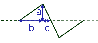 |
mm |
Slope
| Parameter Name | Description | Value |
|---|---|---|
| Slope | Defines the parameters of the slope dimension symbol. a = width b = height c = open/closed profile 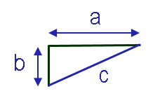 |
mm |