About Configuring the Rebar Position | ||||||
|
| |||||
While creating a rebar, you perform several operations including edit the axis system, adjust the inputs, handle extremities by specifying start and end hooks, relimit the bars, and finally create bends.
The figure below illustrates the rebar position configuration process and provides an overview of the associated tools.
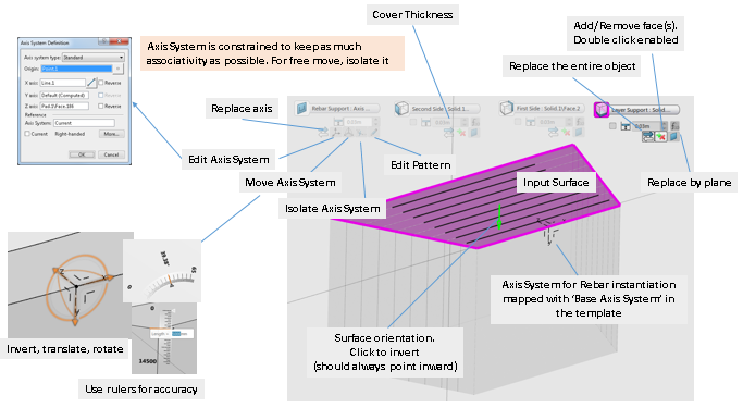
When creating a rebar, a preview shows the rebar layer as you move the mouse over the concrete design. The first step consists in selecting the first bar plane that is the plane on which this bar is laid. In most cases, the first bar is perpendicular to the pattern's direction. The second step involves determining the axis position precisely using the dedicated flag. The last step consists in selecting other surfaces to adjust the rebar layer so that it fits the concrete shape.
- About Flags
- Dedicated flags that provide more options help you perform operations to define the rebar position. For more information about these options, see Context Toolbars.
- Color Coding
- A color code is applied to the various rebar supports also referred to as roles:
- The rebar support
 (axis system) is colored in
light blue.
(axis system) is colored in
light blue. - The first side ( that is the right surface)
 is colored in green .
 - The layer support (that is the bottom surface)
 is colored in pink.
 - The cap surface (that is the top surface)
 is colored in dark blue.
 - The second side (
 colored in yellow).
 - The front side.
- The rebar support
- Patterning and Rebars
- Configuring the rebar pattern consists in specifying the count, the pattern type, and determine the spacing distance between the bars. Direct manipulation tools can be enabled and accessed by clicking the Pattern tab in the Rebar Creation dialog box. For more information, see About Rebar Patterning and About the Rebar Creation Assistant.
