A fatigue crack growth analysis for linear elastic response:
is a quasi-static analysis on a structure subjected to subcritical cyclic loading;
is characterized by the fracture energy release rate;
uses a classical incremental method for each loading cycle;
does not make use of the Fourier representation of the displacement solutions as is the case
for the direct cyclic framework;
can be associated with thermal as well as mechanical loading;
models propagation of a discrete crack along an arbitrary,
solution-dependent path without remeshing in the bulk brittle material based on
the principles of linear elastic fracture mechanics
(LEFM) with the extended finite element
method;
models progressive delamination growth along a predefined path at the
brittle material interfaces in laminated composites;
uses the damage extrapolation technique to accelerate the fatigue
crack growth analysis;
accounts for the change of contact conditions and geometric nonlinearity; and
can be simplified to accelerate the crack growth analysis in some special cases.
The fatigue crack growth analysis capability in Abaqus/Standard is a quasi-static analysis on a structure subjected to subcritical cyclic loading. You
can use the fatigue crack growth procedure to simulate two different classes of problems
depending on the crack location.
At the brittle interface of laminated composites the cyclic loading leads to
interface strength degradation causing fatigue delamination growth. The onset
and growth of delamination are characterized by the fracture energy release
rate at the crack tip based on the Paris law (see
Paris, 1961).
The other class of problems is for brittle bulk materials, in which the
cyclic loading leads to material strength degradation causing fatigue crack
growth along an arbitrary path. Such an approach is based on the principles of
linear elastic fracture mechanics with the extended finite element method. The
onset and growth of the crack are also characterized by the fracture energy
release rate at the crack tip based on the Paris law (see
Paris, 1961).
If both failure mechanisms (that is, discrete fatigue crack growth in the bulk brittle material
and fatigue delamination growth at the brittle material interfaces) are considered within a
single analysis, the most critical failure mechanism governs the actual fatigue crack growth
and the damage in the region governed by the less critical failure mechanism is scaled
proportionally. In the vicinity where fracture or debonding occurs, linear elastic
deformation or the small scale yielding condition must be satisfied.
A fatigue crack growth analysis step can be the only step in an analysis,
can follow a general or linear perturbation step, or can be followed by a
general or linear perturbation step. Multiple fatigue crack growth analysis
steps can be included in a single analysis. The fatigue crack growth procedure
supports only constant amplitude loading—thermal, mechanical, or a combination
of thermal and mechanical. You must specify the cyclic loading amplitude curves
for a single loading cycle. Such a general formulation allows a wide range of
loading histories such as contact or complex combinations of asynchronous
loadings within a cyclic loading definition. For example, a mechanical pressure
and a temperature with peaks/troughs in each can occur at different times
within a single loading cycle.
The crack growth is governed by the Paris law:
where and are material constants.
For enriched elements, an equivalent form of the above Paris law based on the stress
intensity factor is also available:
In the above expression, is the total maximum strain energy release rate (as opposed to the strain
energy release rate change over a cycle used in the original form of the Paris law), while and are material parameters that depend on mode-mix and stress ratios. Abaqus does not support the above form of the crack growth rate equation directly, but instead
allows specification of as a tabular function of , the mode-mix ratio, and the stress ratio.
In addition, a user-defined fatigue crack growth law can be specified in
user subroutine
UMIXMODEFATIGUE.
You specify the maximum numbers of cycles, ,
when you define the fatigue crack growth analysis step.
Input File Usage
Use the following option to specify a general fatigue crack
growth analysis with constant amplitude:
FATIGUE, TYPE=CONSTANT AMPLITUDE (default)
first data line
, ,
Simplifying the Fatigue Crack Growth Analysis
The general fatigue crack growth analysis procedure described above can be
simplified in some special cases if the following conditions are satisfied:
the peak or the trough value of the strain energy release rate,
G, always occurs when the applied load,
P, reaches its maximum or minimum value;
the strain energy release rate is proportional to the square of the
applied load, P; and
the contact conditions remain unchanged during a single loading cycle.
For the simplified fatigue crack growth analysis, you can apply a constant load with a magnitude
of (for the fracture energy release rate–based Paris law) or (for the stress intensity factor–based Paris law), where , is the maximum applied load and is the minimum applied load over a single cycle. At least two increments
are required for each single loading cycle period when the simplified method is used.
Input File Usage
Use the following option to apply a constant load to simplify
the fatigue crack growth analysis:
Controlling the Incrementation during the Cyclic Time Period
Several automatic incrementation methods are available. Alternatively, you
can use fixed time incrementation.
Automatic Incrementation
If you specify only the maximum allowable nodal temperature change in an
increment, the time increments are selected automatically based on this value.
Abaqus/Standard
restricts the time increments to ensure that the maximum temperature change is
not exceeded at any node during any increment of the analysis.
For rate-dependent constitutive equations you can limit the size of the
time increment by the accuracy of the integration. The user-specified accuracy
tolerance parameter limits the maximum inelastic strain rate change allowed
over an increment:
where
t
is the time at
the beginning of the increment,
is the time increment (so that
is the time at the end of the increment), and
is the equivalent creep strain
rate.
To achieve sufficient accuracy, the value chosen for the accuracy
tolerance parameter should be on the order of
for creep problems (where
is an acceptable level of error in the stress and E is a
typical elastic modulus) or on the order of the elastic strains for
viscoelasticity problems.
If rate-dependent constitutive equations are used in combination with a
varying temperature, both controls can be used simultaneously.
Abaqus/Standard
chooses the increments that satisfy both criteria.
If neither the accuracy tolerance parameter nor the maximum allowable
nodal temperature change is specified,
Abaqus/Standard
selects increment sizes based on computational efficiency.
Input File Usage
Use the following option to indicate the time increment
sizes based on computational efficiency:
Defining the Time Points at Which the Response Must Be Evaluated
The user-defined time incrementation for a fatigue crack growth analysis
step can be augmented or superseded by specifying particular time points in the
loading history at which the response of the structure should be evaluated.
This feature is particularly useful if you know prior to the analysis at which
time points in the analysis the load reaches a maximum and/or minimum value or
when the response will change rapidly. An example is the analysis of the
heating/cooling thermal cycle of an engine component where you typically know
when the temperature reaches a maximum value.
When time points are used with fixed time incrementation, the time
incrementation specified for the fatigue crack growth step is ignored; instead,
the time incrementation precisely follows the specified time points. If time
points are used with automatic incrementation, the time incrementation is
variable; however, the response of the structure is evaluated at the specified
time points.
The time points can be listed individually, or they can be generated
automatically by specifying the starting time point, ending time point, and
increment in time between the two specified time points.
Input File Usage
Use the following options to list the time points
individually:
Use the following options to generate the time points
automatically:
TIME POINTS, NAME=time points name, GENERATEFATIGUE, TIME POINTS=time points name
Discrete Crack Propagation along an Arbitrary Path with the Extended Finite Element Method
Fatigue crack growth analysis in
Abaqus/Standard
allows the modeling of discrete crack growth along an arbitrary path based on
the principles of linear elastic fracture mechanics with the extended finite
element method. You complete the definition of the crack propagation capability
by defining a fracture-based surface behavior and specifying the fracture
criterion in enriched elements. The fracture energy release rates at the crack
tips in enriched elements are calculated based on the modified virtual crack
closure technique (VCCT).
VCCT
uses the principles of linear elastic fracture mechanics. Therefore,
VCCT
is appropriate for problems in which brittle fatigue crack growth occurs,
although nonlinear material deformations can occur somewhere else in the bulk
materials. For more information about defining fracture criteria and
VCCT
in enriched elements, see
Modeling Discontinuities as an Enriched Feature Using the Extended Finite Element Method.
To accelerate the fatigue crack growth analysis, the damage extrapolation
technique is used, which advances the crack by at least one element length
after each completed cycle.
Onset and Growth of Fatigue Crack
The onset and growth of fatigue crack at an enriched element are
characterized by using the Paris law, which relates the relative fracture
energy release rate, ,
to crack growth rates. Two criteria must be met to initiate fatigue crack
growth:
one criterion is based on material constants, ,
and the current cycle number, ;
the other criterion is based on the maximum fracture energy release rate,
,
which corresponds to the cyclic energy release rate when the structure is
loaded up to its maximum value.
Once the onset of fatigue crack growth criterion is satisfied at the
enriched elements, the crack growth rate, ,
is a piecewise function based on a user-specified form of the Paris law. The
criteria for fatigue crack onset and growth are discussed in detail in
Modeling Discontinuities as an Enriched Feature Using the Extended Finite Element Method.
If you do not specify the onset criterion,
Abaqus/Standard
assumes that the onset of fatigue crack growth is satisfied automatically.
Damage Extrapolation Technique
If the onset of the crack growth criterion is satisfied at any crack tip in
the enriched element at the end of a completed cycle, ,
Abaqus/Standard
extends the crack length, ,
from the current cycle forward over a number of cycles,
,
to
by fracturing at least one enriched element ahead of the crack tips. Given the
particular fatigue crack growth form of the Paris law (as defined in
Modeling Discontinuities as an Enriched Feature Using the Extended Finite Element Method),
combined with the known element length and likely propagation direction
at the enriched elements ahead of the crack tips, the number of cycles
necessary to fail each enriched element ahead of the crack tip can be
calculated as ,
where
represents the enriched element ahead of the th
crack tip. The analysis is set up to advance the crack by at least one enriched
element per increment after the loading cycle is completed. The element with
the fewest cycles is identified to be fractured, and its
is represented as the number of cycles to grow the crack equal to its element
length, .
The most critical element is completely fractured with a zero constraint and a
zero stiffness at the cracked surfaces at the end of the completed cycle. As
the enriched element is fractured, the load is redistributed, and a new
fracture energy release rate must be calculated for the enriched elements ahead
of the crack tips for the next cycle. This capability allows at least one
enriched element ahead of the crack tips to be fractured after each completed
cycle and precisely accounts for the number of cycles needed to cause fatigue
crack growth over that length.
Progressive Delamination Growth along a Predefined Path at Interfaces
Fatigue crack growth analysis in
Abaqus/Standard
also allows the modeling of progressive delamination growth at the interfaces
in laminated composites. The interface along which the delamination (or crack)
propagates must be indicated in the model using a fracture criterion
definition. The fracture energy release rates at the crack tips in the
interface elements are calculated based on the virtual crack closure technique
(VCCT).
VCCT
uses the principles of linear elastic fracture mechanics. Therefore,
VCCT
is appropriate for problems in which brittle fatigue delamination growth occurs
along predefined surfaces, although nonlinear material deformations can occur
in the bulk materials. For more information about defining fracture criteria
and VCCT,
see
Crack Propagation Analysis.
To accelerate the fatigue crack growth analysis, the damage extrapolation
technique is used, which releases at least one element length at the crack tip
along the interface after each completed cycle. When both brittle fatigue
delamination at interfaces and discrete crack growth in bulk materials are
considered in an analysis, failure occurs first at the weakest link.
Onset and Growth of Fatigue Delamination
The onset and growth of fatigue delamination at a defined crack interface
are characterized by using the Paris law, which relates the relative fracture
energy release rate, ,
to crack growth rates. Two criteria must be met to initiate fatigue
delamination growth:
one criterion is based on material constants, ,
and the current cycle number, ;
the other criterion is based on the maximum fracture energy release rate,
,
which corresponds to the cyclic energy release rate when the structure is
loaded up to its maximum value.
Once the onset of the delamination growth criterion is satisfied at the
interface, the delamination growth rate, ,
is a piecewise function based on a user-specified form of the Paris law. The
criteria for fatigue delamination onset and growth are discussed in detail in
Fatigue Crack Growth Criterion.
If you do not specify the onset criterion,
Abaqus/Standard
assumes that the onset of fatigue crack growth is satisfied automatically.
Damage Extrapolation Technique at the Interface Elements
If the onset of delamination growth criterion is satisfied at any crack tip
in the interface at the end of a completed cycle, ,
Abaqus/Standard
extends the crack length, ,
from the current cycle forward over a number of cycles,
,
to
by releasing at least one element at the interface. Given the particular
fatigue crack growth form of the Paris law (as defined in
Fatigue Crack Growth Criterion),
combined with the known node spacing
at the interface elements at the crack tips, the number of cycles necessary to
fail each interface element at the crack tip can be calculated as
,
where j represents the node at the
jth crack tip. The analysis is set up to release at least
one interface element per increment after the loading cycle is completed. The
element with the fewest cycles is identified to be released, and its
is represented as the number of cycles to grow the crack equal to its element
length, .
The most critical element is completely released with a zero constraint and a
zero stiffness at the end of the completed cycle. As the interface element is
released, the load is redistributed, and a new relative fracture energy release
rate must be calculated for the interface elements at the crack tips for the
next cycle. This capability allows at least one interface element at the crack
tips to be released after each completed cycle and precisely accounts for the
number of cycles needed to cause fatigue crack growth over that length.
Controlling Element Fracture
In the following discussion, the terms damage, fracture, and debonding are used in a
generic sense to describe the process by which the internal forces at the crack-tip nodes
are reduced to zero as they transition from an uncracked to a fully cracked state. At the
end of each cycle, Abaqus utilizes the stress state at the nodes of the current crack front to determine the state
of damage at each node. The following fundamental assumptions govern the fracture process:
The most critical element ahead of the current crack front undergoes complete
damage.
The total cycle count increases by , the number of cycles (based on the Paris law) needed to fracture the
most critical element.
In addition to elements forecast to be fully or almost fully damaged after cycles, additional elements are also allowed to partially fracture if
they are within certain tolerances (described below) in the current cycle.
For the discussion that follows, it is convenient to introduce a damage variable that is
defined in an “incremental” (defined in terms of cycle increments) framework as:
with
where
and
are the scalar damage variables at the end of cycles and , respectively, and
is the length of the element ahead of a current crack front
node.
The value of varies between 0 (undamaged state) and 1 (fully damaged state), with
intermediate values indicating partial damage at a crack-tip node. At the beginning of the
analysis (), the initial damage at each crack-tip node is . At the end of the first completed cycle increment, , the crack-tip node for the most critical element satisfies the condition , and, hence, is fully released.
For other crack-tip nodes, , and these nodes are either undamaged or only partially damaged. The
partial damage is governed by the damage variable, . Abaqus reduces the effective length of partially damaged elements as:
The reduced effective length is used for the next crack growth calculations based
on the Paris law.
Two criteria are available to control the partial fracture of the elements ahead of the
current crack front:
A cycle-based criterion that is based on a tolerance value, .
A damage-based criterion that is based on a tolerance value, .
If neither tolerance is specified, the damage-based criterion, with a default , is assumed to be in effect. If both tolerances are specified, the
damage-based tolerance takes precedence. Using a damage-based tolerance allows you to choose
the tolerance independent of the cycle increment size during the analysis.
In addition to satisfying one of the two criteria outlined above, crack front nodes are
only fractured partially if such fracture helps ensure overall self-similar crack
propagation, which is a fundamental assumption of the VCCT method. In other words, not all nodes that are eligible for partial
fracture based on either the cycle-based or the damage-based criterion actually undergo
partial fracture.
Cycle-Based Criterion for Partial Damage
For a cycle-based criterion, all elements ahead of the current crack front that satisfy
the following criterion are eligible for partial fracture:
A typical value of that provides a balance between accuracy and performance is 0.1.
Input File Usage
Use the following option to specify a cycle-based tolerance for determining the
elements that are eligible for partial fracture:
Influence of Tolerance Parameters on Accuracy and Performance
If a small tolerance is specified, fewer elements along the crack front are eligible for
fracture during any given cycle increment . In this case, more cycle increments in total (with a smaller size for
each cycle increment) are required to propagate an initial crack to its final allowable
crack length. This approach results in a more accurate solution, although at a higher
computational cost.
The opposite is true if a large tolerance is specified. In this case, more elements along
the crack front are eligible for fracture during any given cycle increment. Therefore,
fewer cycle increments in total (with a larger size for each cycle increment) are likely
required to propagate an initial crack to its final allowable crack length. This approach
might be computationally more efficient. However, the predicted total number of cycles
taken to propagate an initial crack to its final allowable crack size might be less
conservative. In addition, the use of a very large tolerance (for example, 0.95) might
violate the self-similar crack growth assumption that is fundamental to the
VCCT method, resulting in a jagged (not smoothing) crack front.
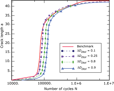
Figure 1 illustrates how the change of tolerance influences the predicted
response of cycle number versus crack length in a mixed-mode fatigue crack growth analysis
when compared to a benchmark solution (Krueger et al, 2020). Reducing the tolerance from 0.25 to 0.1
results in an almost identical response; however, the solution with a tolerance of 0.1 was
computationally more expensive. For a larger tolerance, the predicted total number of
cycles taken to propagate an initial crack to its final allowable crack length is somewhat
nonconservative.
Figure 1. Effect of the tolerance on the predicted response of cycle number versus crack
length.
Initial Conditions
Initial values of stresses, temperatures, field variables,
solution-dependent state variables, etc. can be specified (see
Initial Conditions).
Boundary Conditions
Boundary conditions can be applied to any of the displacement or rotation
degrees of freedom. During the analysis, prescribed boundary conditions in a
general fatigue crack growth step must have an amplitude definition that is
cyclic over the step: the start value must be equal to the end value (see
Amplitude Curves).
However, prescribed boundary conditions in a simplified fatigue crack growth
analysis must have a constant value. If the analysis consists of several steps,
the usual rules apply (see
Boundary Conditions).
At each new step the boundary condition can either be modified or completely
defined. All boundary conditions defined in previous steps remain unchanged
unless they are redefined.
Loads
The following loads can be prescribed in a fatigue crack growth analysis
step:
Concentrated nodal forces can be applied to the displacement degrees of
freedom (1–6); see
Concentrated Loads.
Distributed pressure forces or body forces can be applied; see
Distributed Loads.
The distributed load types available with particular elements are described in
the
Abaqus Elements Guide.
During the general fatigue crack growth analysis each load must have an
amplitude definition that is cyclic over the step where the start value must be
equal to the end value (see
Amplitude Curves).
However, each load must have a constant value in a simplified fatigue crack
growth analysis. If the analysis consists of several steps, the usual rules
apply (see
About Loads).
At each new step the loading can either be modified or completely defined. All
loads defined in previous steps remain unchanged unless they are redefined.
Predefined Fields
The following predefined fields can be specified in a fatigue crack growth
analysis step, as described in
Predefined Fields:
Temperature is not a degree of freedom in a fatigue crack growth analysis step, but nodal
temperatures can be specified as a predefined field. The temperature values specified in
a general fatigue crack growth analysis must be cyclic over the step: the start value
must be equal to the end value (see Amplitude Curves). If the
temperatures are read from the results file, you should specify initial temperature
conditions equal to the temperature values at the end of the step (see Initial Conditions).
Alternatively, you can ramp the temperatures back to their initial condition values, as
described in Predefined Fields. Any
difference between the applied and initial temperatures causes thermal strain if a
thermal expansion coefficient is given for the material (Thermal Expansion). The
specified temperature also affects temperature-dependent material properties, if any. In
a simplified fatigue crack growth analysis, the temperature values specified must be
constant.
The values of user-defined field variables can be specified. These
values affect only field-variable-dependent material properties, if any. The
field variable values specified in a general fatigue crack growth analysis must
be cyclic over the step. The field variable values must be constant in a
simplified fatigue crack growth analysis step.
Material Options
Most material models that describe mechanical behavior are available for use
in a fatigue crack growth analysis. The inelastic definition in a material
point must be used in conjunction with the linear elastic material model (Linear Elastic Behavior),
the porous elastic material model (Elastic Behavior of Porous Materials),
or the hypoelastic material model (Hypoelastic Behavior).
The following material properties are not active during a fatigue crack growth analysis: acoustic
properties, thermal properties (except for thermal expansion), mass diffusion properties,
electrical conductivity properties, piezoelectric properties, and pore fluid flow
properties.
However, in the vicinity where fracture or debonding occurs, linear elastic
deformation or the small scale yielding condition must be satisfied.
Elements
Any of the stress/displacement elements in Abaqus/Standard can be used in a fatigue crack growth analysis (see Choosing the Appropriate Element for an Analysis Type). However, when
modeling fatigue crack growth based on the principles of linear elastic fracture mechanics
with the extended finite element method, only first-order continuum stress/displacement
elements and second-order stress/displacement tetrahedral elements can be associated with an
enriched feature (see Modeling Discontinuities as an Enriched Feature Using the Extended Finite Element Method).
The following whole element variables are available with the extended finite
element method:
STATUSXFEM
Status of the enriched element. (The status of an enriched element is 1.0 if
the element is completely cracked, 0.0 if the element is not. If the element is
partially cracked, the value lies between 1.0 and 0.0.)
CYCLEINIXFEM
Number of cycles to initialize the crack at the enriched element.
CYCLEXFEM
Number of cycles to fracture at the enriched element.
ENRRTXFEM
All components of strain energy release rate.
The following
additional surface output variables can be also requested along a predefined
path at interfaces:
CSDMG
Overall value of the scalar damage variable.
BDSTAT
Bond state. The bond state varies between 1.0 (fully bonded) and 0.0 (fully
unbonded).
CYCLE
Number of cycles to debond.
ENRRT
All components of strain energy release rate.
Limitations
The fatigue crack growth procedure supports only constant amplitude
loading—thermal, mechanical, or a combination of thermal and mechanical.
Several fatigue crack growth analysis steps can be used for an analysis with
variable amplitude loading with each step having a constant amplitude loading.
Significant inaccuracy in fatigue prediction can occur if the fatigue
procedure is used for cases that depart significantly from linear elastic
response near a crack. See
Low-Cycle Fatigue Analysis Using the Direct Cyclic Approach
for discussion of simulation fatigue crack growth involving ductile materials.
Input File Template
The
following is an example using the general fatigue crack growth analysis
procedure:
HEADING
…
ENRICHMENT, TYPE=PROPAGATION CRACK, INTERACTION=INTERACTION,
ELSET=ENRICHED
BOUNDARYData lines to specify zero-valued boundary conditionsINITIAL CONDITIONSData lines to specify initial conditionsAMPLITUDEData lines to define amplitude variations
**
MATERIALOptions to define material propertiesSURFACE, INTERACTION=INTERACTIONSURFACE BEHAVIORFRACTURE CRITERION, TYPE=FATIGUEData lines to define material constants used in the Paris law and fracture criterion in the bulk
material for enriched elements
**
SURFACE, NAME=secondaryData lines to define the secondary surface at the delamination interfaceSURFACE, NAME=mainData lines to define the main surface at the delamination interfaceCONTACT PAIRsecondary, mainTIME POINTS, NAME=T1
**
STEP (,INC=)
Set INC equal to the maximum number of increments in a single loading cycleFATIGUE, TYPE=CONSTANT AMPLITUDE, TIME POINTS=T1Data line to define time increment, cycle time, minimum time increment allowed, and maximum time increment allowedData line to define minimum increment in number of cycles, maximum increment in number of cycles, total number of cycles, , tolerance for the least number of cycles to fractureDEBOND, SECONDARY=secondary, MAIN=mainFRACTURE CRITERION, TYPE=FATIGUEData lines to define material constants used in the Paris law and fracture criterion at the interface
**
BOUNDARY, AMPLITUDE=
Data lines to prescribe zero-valued or nonzero boundary conditionsCLOAD and/or DLOAD, AMPLITUDE=
Data lines to specify loadsTEMPERATURE and/or FIELD, AMPLITUDE=
Data lines to specify values of predefined fields
**
END STEP
The following is an example using the simplified fatigue
crack growth analysis procedure:
HEADING
…
ENRICHMENT, TYPE=PROPAGATION CRACK, INTERACTION=INTERACTION,
ELSET=ENRICHED
BOUNDARYData lines to specify zero-valued boundary conditionsINITIAL CONDITIONSData lines to specify initial conditionsAMPLITUDEData lines to define a constant load equal to
**
MATERIALOptions to define material propertiesSURFACE, INTERACTION=INTERACTIONSURFACE BEHAVIORFRACTURE CRITERION, TYPE=FATIGUEData lines to define material constants used in the Paris law and fracture criterion in the bulk
material for enriched elements
**
SURFACE, NAME=secondaryData lines to define the secondary surface at the delamination interfaceSURFACE, NAME=mainData lines to define the main surface at the delamination interfaceCONTACT PAIRsecondary, mainTIME POINTS, NAME=T1
**
STEP (,INC=)
Set INC equal to the maximum number of increments in a single loading cycle (at least two increments are required)FATIGUE, TYPE=SIMPLIFIED, TIME POINTS=T1Data line to define time increment, cycle time, minimum time increment allowed, and maximum time increment allowedData line to define minimum increment in number of cycles, maximum increment in number of cycles, total number of cycles, , tolerance for the least number of cycles to fractureDEBOND, SECONDARY=secondary, MAIN=mainFRACTURE CRITERION, TYPE=FATIGUEData lines to define material constants used in the Paris law and fracture criterion at the interface
**
BOUNDARY, AMPLITUDE=
Data lines to prescribe zero-valued or nonzero boundary conditionsCLOAD and/or DLOAD, AMPLITUDE=
Data lines to specify loadsTEMPERATURE and/or FIELD, AMPLITUDE=
Data lines to specify values of predefined fields
**
END STEP
References
Deobald, L., G. Mabson, S. Engelstad, M. Rao, M. Gurvich, W. Seneviratne, S. Perera, T. O'Brien, G. Murri, J. Ratcliffe, C. Davila, N. Carvalho, and R. Krueger, “Guidelines
for VCCT-Based Interlaminar Fatigue and Progressive Failure Finite Element
Analysis,” NASA/TM-2017-219663, 2017.
Krueger, R., L. Deobald, and H. Gu, “A Benchmark Example for Delamination Growth Predictions Based on the Single Leg Bending Specimen under Fatigue Loading,” Advanced Modeling and Simulation in Engineering Sciences, vol. 7, no. 11, 2020.
Paris, P., M. Gomaz, and W. Anderson, “A
Rational Analytic Theory of Fatigue,” The
Trend in
Engineering, vol. 15, 1961.
Ratcliffe, J., and W. Johnston, “Influence of Mixed Mode I-Mode II Loading on
Fatigue Delamination Growth Characteristics of a Graphite Epoxy Tape
Laminate,” Proceedings of American Society
for Composites 29th Technical
Conference, 2014.