Graphic Replacement for Panels | ||||
|
| |||
You can customize generative view style parameters for panel (shell, deck, longitudinal bulkhead, transverse bulkhead, parametric panel). These parameters are shared by all structure apps. Customizing parameters in this file affects the appearance of your drawings and is an administrator's task.
For the sample GVS files, see 3DEXPERIENCE Native Apps Content Reference Guide: Samples for Drafting.
- You can generate the drawing of the parametric panel by selecting it independently or by selecting the plate to which it is connected.
- Only the parametric panel connected to the master plate is generated in drawing.
Sample XML File
In the sample XML file, generative view style parameters for plates are located towards the bottom of the file under StructureObjects.
Plate: Primary
- Draw
- Graphic Replacement
- LogicalViewGeneration
- ViewType
- SpecifyViewType
Lets you specify the view type.
- SideView
- ResultType
- NearSide
- FarSide
- AccrossSide
- AnnotationTextStyle
- MaterialExtrusionSymbol
- SeamSymbol
- PlanningBreakSymbol
- StandAlonePlateSymbol
- AnyView
- ResultType
- NearSide
- FarSide
- AccrossSide
- AnnotationTextStyle
- SlotContour
- SeamSymbol
- PlanningBreakSymbol
- TopView
- ResultType
- NearSide
- FarSide
- AccrossSide
- AnnotationTextStyle
- SlotContour
- SeamSymbol
- PlanningBreakSymbol
- Flange
- SpecifyViewType
Plate: Secondary
- Draw
- Graphic Replacement
- ViewType
- SpecifyViewType
Lets you specify the view type.
- SideView
- ResultType
- NearSide
- FarSide
- AccrossSide
- AnnotationTextStyle
- MaterialExtrusionSymbol
- SeamSymbol
- PlanningBreakSymbol
- StandAlonePlateSymbol
- AnyView
- ResultType
- NearSide
- FarSide
- AccrossSide
- AnnotationTextStyle
- SlotContour
- SeamSymbol
- PlanningBreakSymbol
- SpecifyViewType
- Draw
- Specifies whether to draw the plate.
By default, the value is Yes.
- GraphicReplacement
- Specifies whether to use the graphic replacement.
By default, the value is No.
- LogicalViewGeneration
- PropagationOnSupport
- Specifies whether to retrieve all the objects that are in clash with the canonical molded
surface of the primary plates.
 By default, it is
No.
By default, it is
No. - MultiResult
- Specifies whether to draw multi-results. By default, it is No.
- OffsetTolerance
- Specifies the offset value used to include or exclude objects using the same support with different offsets. By default, the value is 0.0.
- ViewType
- There are three view types for plates: SideView, AnyView and TopView.
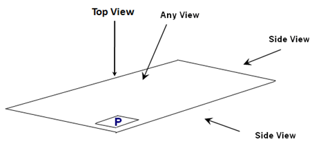
For a curved plate, the view type is always AnyView.
Each of these views have: NearSide, FarSide, and AccrossSide parameters, and AnnotationTextStyle parameters. See Near Side, Far Side, and Across Side View Types and Annotation Text Style.
Important: The logical and functional tolerance and annotation (FTA) section are the only modes, where you can compute AcrossSide parameters, which are similar to NearSide and FarSide parameters. The default values are same as NearSide values. If you are not interested in an AcrossSide analysis, you need to synchronize Near and Across Linetype and LineThickness. - MaterialExtrusionSymbol
- Draw
- Specifies whether the far side plate be drawn. By default, it is Yes.
- MaterialExtrusionMode
- Specifies the material throw orientation. Values are:
- 1 = Tick mark (true width)
- 2 = Throw orientation (symbolic)

- 3 = Tick mark and throw orientation

- 1 = Tick mark (true width)
- SymbolLocation
- Specifies the location on the line representation of the plate where the throw orientation will be drawn. Values are:
- 1 = Start
- 2 = Middle
- 3 = End
- MaterialThroughOrientationSymbol
- ChapterName
- Indicates the name of the chapter containing material through orientation symbols within the Drawing Symbol Structure Catalog.
- SymbolName
- Indicates the name of the detail within the catalog to instantiate for material through orientation.
- ReferenceScale
- Indicates the scale factor to be applied to the symbol as drawn. By default, it is 1.
- TickMarkSymbol
- Specifies the length of tick mark when drawing a tick mark. By default, it is 5.0 millimeters.
- StandAlonePlateSymbol
- Represents the standalone plate by symbol or annotation text style when it is limited by a stiffener.
- SymbolDetail
- Draw
- Specifies whether to draw the symbol for standalone plate. By default, the value is Yes.
- ChapterName
- Indicates the name of chapter containing standalone plate symbols within the Drawing Symbol Structure Catalog. By default, the chapter name is StandAlonePlate.
- SymbolName
- Indicates the name of detail within the catalog to instantiate for standalone plate. By default, the name is Default_StandAlonePlate_Symbol.
- ReferenceScale
- Indicates the scale to be set for the standalone plate details. By default, the value is 1.0.
- SymbolATS
- Draw
- Specifies whether to draw the annotation text style (ATS) for standalone plate. By default, the value is No.
- ATS_AutoPosition
- Specifies whether the standalone plate annotation text style has a leader. By default, the value is No.
- ATS_CharacterOffset
- Indicates the integer value. The non zero integer values includes a leader to the characters. By default, the value is 0.
- ATS_Attribute
- Indicates the attributes of annotation text styles. If there are multiple attributes, they are separated by a comma. By default, the value is sfm_plate_name.