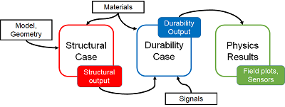
The full process of creating a fatigue analysis includes two sets of steps: one set you
perform in the structural analysis case and another you perform in the durability
analysis case.
Configure the Structural Analysis Case
Perform the following steps to configure an existing structural
analysis case for subsequent use in a durability calculation:
-
Apply an appropriate material to the model. For more information, see Material
Palette.
Choose a material with fatigue options defined in its simulation domain to share a model
between structural and durability analysis cases. For more information,
see fe-safe Durability Properties.
The fatigue options also include the configuration of a fatigue algorithm, which can
describe finite life or infinite life behavior. The app requires a fatigue algorithm and the associated fatigue options in
the simulation domain to run the durability analysis case. For more
information, see About Fatigue Algorithms.
You can apply a new material after the initial solve of the structural case, but making such
a change invalidates the stress results and requires you to run the
simulation again. For more information, see About Analysis Cases.
- Optional:
Revisit the mesh to determine whether it is suitable for a fatigue analysis. You might need
to switch to the Structural Model Creation
app to review the mesh. For example, you might need to run a mesh
convergence study in the area of interest to make sure the mesh density
captures stresses accurately. As with material assignment, changes to a
mesh invalidate previously solved structural analysis cases.
-
Configure the output requests for the solid geometry in your
model.
Most fatigue failures occur on the exterior surface of a solid body. As a result, you
should use stresses at element-nodes or stresses averaged at nodes
rather than those at interior (Gauss) integration points to ensure the
most accurate fatigue life prediction.
For structural analyses that involve elastic-plastic material behavior, you should use
elements with nodal integration elements.
For structural analyses that involve elastic behavior only, you can use elements with nodal
integration points or those with interior (Gauss) integration points. In
the latter case, the app extrapolates the stresses to the element nodes
(without nodal averaging) before it performs the fatigue calculations,
and the fatigue analysis results are output at the element nodes.
-
Configure the output requests for the shell geometry in your
model.
As with output requests for the solid geometry, confirm that the stresses are output on the
top and the bottom.
Define the Durability Analysis Case
Perform the following steps to define the durability analysis case
for the fatigue analysis.
-
Create a durability analysis case.
For more information, see About Durability Analysis Cases.
-
Select the finite element model that you want to use for the durability analysis case. If
more than one FEM representation is present in the simulation, choose
the FEM representation that is shared with the structural analysis case
to be used in the fatigue loading.
For more information, see Applying a Finite Element Model to a Simulation.
-
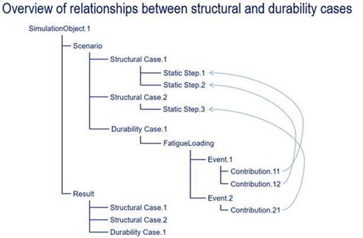
Define the fatigue loading history. Fatigue loading defines one or more events that describe
the fatigue load history. These events refer to frames from steps
defined in the structural cases. You do not need to solve the structural
cases before you define fatigue loading.
Define the Defining Fatigue Loading.
- Optional:
Define the surface finish. You can specify a base surface finish for the entire model or a
local surface finish for a specific region of your model. A local
surface definition supersedes the base surface finish where they
overlap.
For more information, see Defining Surface Finishes.
-
The app
generates durability output automatically.
The app calculates field output for fatigue at the same locations
requested in the structural analysis case.
The variables that are output depend on the fatigue algorithm you chose in the
fatigue-related material options for the materials applied to the model.
For more information, see About Fatigue Algorithms.
Run the Simulation Job
When you run the simulation, you can run the durability analysis case separately from the
structural analysis cases, or you can run them both in sequence. For more
information, see Running a Simulation from an App.
The Run dialog box lists the individual analysis cases in order.
Select the check boxes next to the analysis cases that you want to run, and
specify the number of CPUs you want to allot to the solver for each analysis
case. From the Units options, specify that the simulation
runs using MKS units.
Postprocessing
Physics Results Explorer enables you to display output from the structural analysis case and
durability analysis case. For more information about the results available for
durability analyses, see About Durability Output. For information about the results output for
structural analyses, see the Abaqus Output Guide.

