Right-click the space root and select Insert > Space System.
The Space System dialog box appears.
Select Space system with cutting elements in the
Space System Options tab and click
OK.
The space system is created in the tree under the space root. The SpaceManager.x node is
available under space system.
Double-click the space system representation to activate it.
From the Operations section of
the action bar, clickSpace Manager.
The Space Manager with Cutting Elements dialog
box appears.
Optional:
In the Bounding box box, select a bounding box from
the 3D area or tree.
Notes:
The bounding box from the Space Referential is automatically selected
if the reference plane system is set in the resource table.
You can replace or remove the bounding
box.
If no bounding box is selected, you need to specify the extreme
elements manually. See Step 9.
In the External volume box, select a predefined
volume from the 3D area or tree.
In the Internal volumes box, select predefined
volumes from the 3D area or tree.
Under Cutting Families, add a cutting family and the
corresponding cutting elements.
Click Add Cutting Family to insert a new line for a cutting family.
Enter the name of the cutting family (for example,
Deck).
Select the required cutting elements from the 3D area or tree.
Note:
If no bounding box is set, you need to specify the
extreme elements (minimum element and maximum element) first.
Click to set the extreme elements in the
Cutting Elements dialog box.
Leader
Description
1
Volume
2
Cutting elements
3
Minimum cutting
element
4
Maximum cutting
element
5
Direction (X or Y or
Z)
When the bounding box is selected, the extreme elements
and the direction are automatically set when you select the
first cutting element.
Notes:
The selected cutting elements are displayed under
Elements.
You can also select the direction first and then select
the cutting elements in that direction.
Recommendation:
Do not change the direction
after selecting the cutting elements.
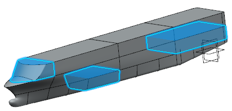
You can click to create cutting elements on the fly. These cutting
elements are aggregated under the space system
representation.
To edit the cutting element created through
Space Manager, you can either
double-click it in the tree or 3D area, or select the
cutting element in the Cutting
Elements dialog box and click .
While creating the cutting elements, the default limit
volume for cutting elements is set through
Space Manager as follows:
Space
Manager
Limit Volume
for Cutting Element
Bounding Box
External Volume
Set
Set
Bounding box
Not set
Set
External volume
Not set
Not set
-
You can change the limit in the
Cutting Element dialog box if
required.
Refer the above steps (a to c) to create the other cutting
families.
Click OK.
All the space cells are generated under the SpaceCell
Set.x node.
Space Cells
Modify the Space Cells Using the Space Manager Command
You can modify the space cells by changing the inputs such as external volume, internal volumes, cutting family, and cutting elements.
Before you begin: Create space cells.
From the Operations section of the action bar, click Space Manager.
The Space Manager with Cutting Element dialog box
appears.
In the External Volume box,
change the input of the external volume.
In the Internal Volume box,
change the inputs of the internal volume.
Click available next to the Internal Volume box.
The Internal Volumes dialog box appears. It shows the internal volumes selected in the box.
Select a check box to choose an internal volume.
The original input of the internal volume is highlighted in the 3D area and tree.
Click Replace and select a new volume from the 3D area or tree to substitute the internal volume.
To remove one or more internal volumes, select the corresponding check boxes and click Delete.
Under Cutting Family, add or remove a cutting family.
Click Add Cutting Family to insert a new line for a cutting family.
Enter the name of a cutting family (for example, Firezone).
Select the required cutting elements from the 3D area or tree.
To remove one or more cutting families, select the corresponding check boxes and click Delete Cutting Family.
Under Cutting Family, edit or remove the cutting elements.
Click available next to the cutting family.
The Cutting Elements dialog box appears. It shows the cutting elements selected in the cutting family.
Select a check box to choose a cutting element.
The original input of the cutting element is highlighted in the 3D area and tree.
Click to edit the cutting element.
Only the cutting elements created through Space Manager can be edited
from the Cutting Elements dialog box.
To remove one or more cutting elements, select the corresponding check boxes and click Delete.
Click OK.
The space cells are updated as per the changes in the inputs of the space manager.
Modify the Space Cells Using the PLM Update Command
You can edit the inputs of the space manager and update the space system instance to modify the space cells.
Before you begin: Create space cells.
Edit the inputs of the space manager.
Right-click a cutting element and select Selected objects > Edit
Cutting Element.
The Edit Cutting Element dialog box
appears.
Perform the necessary changes.
Click OK.
The cutting element is modified according to the specified changes.
Note:
The inputs can be taken from the same representation as that of the space manager or from a different representation.
Update the space system instance.
A progress bar is displayed, informing you the update status of the space cells. The space cells are updated as per the changes in the inputs of the space manager.
 . The Space System dialog box appears.
 .
The Space Manager with Cutting Elements dialog box appears.
.
The Space Manager with Cutting Elements dialog box appears. to insert a new line for a cutting family.
 to set the extreme elements in the
Cutting Elements dialog box.
to set the extreme elements in the
Cutting Elements dialog box.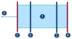
 and select a new volume from the
  .
.