Generate a Modelica Model from a Kinematic Mechanism, Using a
Command
You can generate a Modelica model from a kinematic mechanism
of a physical product, using a command.
-
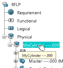
From the top bar, search for the physical product. For
example, you can search for a physical product with the name
Robot_Product by typing
prd:*Robot_* in the Search
field and click Search
 . .
For more information about searching, see 3DEXPERIENCE
Platform: Native Apps Top Bar.
The Search Results
panel appears.
-
To open both the physical and logical parts of the product,
right-click it in the
Search Results
panel
and select
 . .
The product is opened in authoring mode.
- Optional:
To analyze the masses and inertia of the 3D parts, do the
following:
-
In the
tree,
double-click the root node of the physical product to select it.
An example of selection:
-
From the
Tools section of the
action bar,
click
B.I. Essentials
 . .
The
B.I.
Essentials
dialog box appears.
-
In the
B.I.
Essentials
dialog box, select
Weight Definition.
- The result or
the analysis appears in the
B.I.
Essentials
dialog box.
- An information
message appears displaying links.
For more information about weight definition, see
Weight Analysis
Users´s Guide: Defining Weight: Launching Weight Definition.
- Optional:
Compute the masses and inertia of the 3D parts.
-
In the information message, click
Click this hyperlink to update the weight of this
element considering each child weight declared in the system.
The weight attributes table appears.
-
In the weight attributes table, click
Update to perform a heavy update.
For more information about the weight attributes table and
the corresponding commands, see
Weight Analysis
Users´s Guide: Defining Weight: About Defining Weight: About the Weight
Attributes Table.
The result:
- The masses and
inertia are updated.
- An information
message appears displaying links.
- Optional:
To replace computed by declared weight for a part, you can
select different 3D parts and click the link
Click this hyperlink to replace computed by declared
weight.
-
Close the
B.I.
Essentials
dialog box.
- Optional:
If still in the
B.I.
Essentials
app,
to leave it, do the following:
-
From the
Compass,
click
3D Modeling
Apps
.
-
Expand
3DEXPERIENCE
Roles and Apps.
-
Expand
My 3D Modeling apps.
-
Select
Mechanical Systems Design.
-
To store the generated model, create a new Dymola Behavior
library, with the name
MyGeneratedModels. See
Create a Dymola Behavior Library.
The result is:
- You enter the
Dymola Behavior Modeling
app
in a new tab.
- A Dymola Behavior
Library
MyGeneratedModels is created in the new
tab.
-
To work more comfortably between the apps, make both tabs visible on the screen.
-
To generate the Modelica model, from the
Behavior Tools section of the
action bar,
click
Generate from Kinematic
 . .
The Generate from Kinematic dialog box appears. Note:
If you
already have an active model that is generated by this command, the
dialog is prefilled with the setup used for generating this
model.
-
Select the mechanism the following way:
-
Click the Mechanism: field.
-
In the tab where the mechanical model is seen, in the tree, click any joint or command of the mechanism to be used for
Modelica model generation.
The name of the mechanism appears in the Mechanism: field.
-
Select the parent class where the generated model should be
inserted the following way:
-
Click the
Insert In: box.
-
In the
Dymola Behavior Modeling
app,
from the
Package Browser, or from the
tree,
click the package where you want to insert the Modelica representation. In this
scenario, click the library you created.
-
Click the
Output class name: box and enter a name of
the Modelica model to be created. In this scenario, enter
MyGeneratedCylinder.
- Optional:
To generate 3D representations of the shapes, in VRML format:
-
Click
More.
-
Activate
Generate VRML from parts.
If cleared, the generated model includes links to the initial
3D physical model, so it can be animated from the results.
By default, this option is cleared.
In this scenario, keep this option cleared.
- Optional:
To update mass and inertia on parts before translation:
-
Click
More if not already done.
-
Activate
Update mass and inertia on parts before
translation.
By default, this option is cleared.
In this scenario, activate this option.
Mass and inertia on parts are updated before translation.
- Optional:
To include motors attached to commands:
-
Click
More if not already done.
-
Activate
Include motors.
By default, this option is cleared.
In this scenario, keep this option cleared.
- Optional:
To always generate a World component and connect it to fixed
parts, even if the physical model contains published axes:
If not activated, the World model is only generated when the
physical model does not contain any published axes.
-
Click
More if not already done.
-
Activate
Always generate a world component.
By default, this option is cleared.
In this scenario, keep this option cleared.
- Optional:
To rebuild the model when performing any general update command, that is,
any of the commands Update or Update
Assistant, activate the Rebuild at
PLMUpdate.
By default, this option is activated.
A reason for clearing this option can be if you want to compare two
alternatives of a model without risking that an update command updates the
wrong model.
- Optional:
To select how to interpret limiters on revolute, prismatic, and cylindrical
joints when generating the Modelica representation:
-
Click More if not already done.
-
For Joint boundary kind, select any of:
- Warning: When the joint reaches the
limit value, a warning appears and the simulation continues.
- Error: When the joint reaches the
limit value, an error appears and the simulation stops.
- Limiter: A Modelica limiter is
inserted between the flanges of the Modelica joint, limiting
the joint´s movements between the defined limits.
By default, Warning is selected.
In this scenario, keep this option unchanged.
-
Click
OK to start the model generation.
Notes:
- If required, the geometries of the parts involved
in the mechanism are loaded.
- The root physical
model containing the mechanism you selected is set to authoring mode to
retrieve some data from that model.
- If you have
already loaded the physical product in the session, for example, you have
opened it in a tab, only the relevant parts are loaded, not the full product,
to not alter any filtering you have done. If the product is not in the session,
the full product is loaded.
The following is created under the selected target package
MyGeneratedModels: 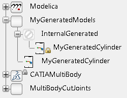
- A class
InternalGenerated that contains the
generated model MyGeneratedCylinder.
Note:
This class is locked, you should not edit this class.
- An extended class
MyGeneratedCylinder.
Note:
This is the
class that you can edit to, for example, extend the model or
replace components.
For the features of the generated classes, for example, handling of
mechanism commands, user-driven Point-Curve joints, dress-up pattern,
published axes, color animation, replacing of components, see About Generating a Modelica Representation of a Mechanism of a Physical Product.
If the physical model contains any publications of Knowledgeware
parameters directly under the product that contains the selected
mechanism, then the corresponding Modelica parameters are created in the
generated model. Those Modelica parameters are exposed in Knowledgeware,
and a formula is created to assign the same value as the value of the
published parameter.
-
To prepare the generated model for testing, do the following:
Usually generated components are just components. They have to be connected to be tested.
Below is a simple example to fix the cylinder before simulating it.
-
In
MyGeneratedModels, create a new model
TestMyGeneratedCylinder. See
Create a New Class or Extend from an Existing Class Using the New Class Command.
-
Instantiate
MyGeneratedCylinder by dragging it into
the
TestMyGeneratedCylinder model.
Note:
Drag the right model, do not drag the locked one.
-
Drag
Modelica.Mechanics.MultiBody.World into
TestMyGeneratedCylinder.
-
Connect the
World component to the main axis frame
of the
MyGeneratedCylinder component.
-
Change the direction of gravity to the negative z axis by
changing the parameter
n of the
World component.
The
MyGeneratedCylinder model is now connected
to a simple "test rig" to test it.
Note:
The structure of libraries is often more elaborate, for
example, it is common to have a separate library for some generated models, and
another library for the use of them in customer models.
-
Simulate the model. See
Simulating a Behavior.
Considering the mass, inertia, and joints, the result is
computed and the corresponding 3D appears.
Notes:
- You can follow 3D
shapes in the animation, see
Managing a 3D Animation.
- You can hide a 3D
shape in the animation by right-clicking it and selecting
Hide.
Note:
The
Hide command works in a toggle mode.
To show the hidden object again, go to the No Show space and apply the command
again. See
Hiding and Showing Objects.
- For a 3D shape,
the 3D shape, the corresponding 2D component in the diagram, and the
corresponding node in the
Variable Browser are highlighted the
same time if clicking on any of them. See
Manage 3D Shapes in a 3D Animation
- You can
right-click a 3D shape or a component in the diagram and select
Show in Variable Browser
 to display and expand the corresponding node in the
Variable Browser. See
Display Component Name for a 3D Shape, and Navigate To It In the Variable Browser. to display and expand the corresponding node in the
Variable Browser. See
Display Component Name for a 3D Shape, and Navigate To It In the Variable Browser.
- You can apply
interference analysis on CATIA Physical 3D shapes. See
Detecting and Handling Physical Clashes.
- When no VRML files
are generated, the simulation of the generated Modelica model directly animates
the 3D representation of the physical model. CATIA 3D shapes and Modelica
transient 3D shapes are displayed together in the same 3D viewer.
Generate a Modelica Model from a Kinematic Mechanism, Using a
Scripting Method
You can generate a Modelica model from a kinematic mechanism
of a physical product, using an Engineering Knowledge Language (EKL) method.
Notes:
- This scenario describes
how to use a scripting method to generate a Modelica model from a kinematic
mechanism of a physical product when both the kinematic mechanism and the
target Modelica package is created and open. The creation of the target
Modelica package is included in the scenario.
- Compared to the scenario
above, in the below scenario you create a behavior with the Modelica target
package, not a stand-alone target package.
- The masses and inertia of the 3D parts are computed
using the command like in the above scenario. This may be computed using
scripting as well.
- The following options are only available when using the command,
see the above scenario:
- Creating 3D representations of the shapes in VRML format
- Generating a World component and connect it to fixed parts if the physical model contains
published axes.
-
From the scenario above, perform Step 1 - Step 6.
Note:
Do not skip any step.
The mechanism is open and the masses and inertia of the
3D parts are computed.
-
On the
Logical node in the
tree,
create a new logical reference containing a Dymola behavior, the following way:
The following is a short description, for details see the
corresponding documentation in
Functional & Logical Design
User´s Guide: Managing Behaviors in Functions and Logical Components.
-
In the
tree,
right-click the
Logical node and select
Insert New Logical Component.
The New Content panel appears.
-
In this panel, expand
Logical and select
Logical Reference.
A logical reference appears under the
Logical node in the
tree.
-
From the
Behaviors section of the
action bar,
click
Insert New Behavior Representation
 . .
-
In the
tree,
click the logical reference you just created.
The New Content panel appears .
-
In this panel, select
Dymola Behavior.
A Dymola behavior is created under the logical
reference.
You have created a logical reference (component) with a
Dymola behavior inside it.
-
In the Dymola behavior, create a package that is to be the target for the
Modelica representation of the mechanism, in the following way:
The following is a short description, for details see Create a New Class or Extend from an Existing Class Using the New Class Command.
-
In the tree, expand the logical reference
you created and double-click the node
MainModel
 . .
The MainModel
represents the
Dymola behavior.
The behavior is opened in the Dymola Behavior Modeling
app.
-
From the Behavior Authoring section of the
action bar, click New Modelica
Class
 . .
The New Class dialog box appears.
-
In this dialog box, do the following:
- In the
Name box enter, for this
scenario,
MyGeneratedModels.
- From the
Class type list, select the
Package type.
- Make sure that the
Insert in box displays
MainModel, otherwise select this model
from the Package Browser.
- Click
Ok to validate the selections.
-
To leave the Dymola Behavior Modeling
app, from the action bar, click Exit
App
 . .
You have created the empty target package
MyGeneratedModels in the Dymola behavior. You can
see it under MainModel in the tree.
-
To start creating the scripting function, do the following:
-
From the
Compass,
click
3D Modeling
Apps
.
-
Expand
3DEXPERIENCE
Roles and Apps.
-
Expand
My 3D Modeling apps.
-
Select
Engineering Rules Capture.
-
From the
action bar,
click
Action
 . .
For full information about actions, see
Engineering Rules Capture
Users Guide: Working with Actions: Creating an Action.
-
In the
Action Editor, do the following:
In this step, you create a script with two arguments corresponding to the target Modelica
package and the source mechanism.
-
In the
Argument list, do the following:
- Right-click
<Add new argument> and select
Add new argument.
- Type
MyTargetModelicaPackage.
- Click the
corresponding
Type box.
- From the list,
double-click
ModelicaPackage
The argument for the target Modelica package is
created.
-
Create a second argument
MySourceMechanism of type
Feature in the same way as the first
argument.
-
Click the text pane to enter it.
-
Press
Enter to go to a new line.
-
Do the following to create the text in the script:
- Type
MyTargetModelicaPackage. and
wait.
When you have entered the period, after a short
while, a list of available methods appear.
- From the list,
double-click
GenerateBehaviorModelFromMechanism.
This text is added.
- Enter a left
bracket.
A tooltip with an argument list appears.
- Type
MySourceMechanism,"MyGeneratedCylinder").
The script is complete, MyGeneratedCylinder is the
name you select for the model to be generated in the
Modelica target package, to be consistent with the task
above.
Note:
If you want to take into account any motors defined in
the physical mechanism, enter instead
MySourceMechanism,"MyGeneratedCylinder",
true)
The script is now
MyTargetModelicaPackage.GenerateBehaviorModelFromMechanism(MySourceMechanism,"MyGeneratedCylinder")
-
Click
OK.
The result is:
- The action is
created.
- In the
tree,
under the
 Relations.1 node, the action is
displayed with an icon
.
Relations.1 node, the action is
displayed with an icon
.
-
In the
tree,
under the
Relations.1 node, right-click
Action.1 and select
.
An
Insert Object dialog box appears for
specifying the arguments of the script.
-
To specify the arguments and run the script:
-
You can leave the Name blank.
-
In the tree, click
MyGeneratedModels to specify the target
Modelica package for the generation.
-
In the tree, under the
Physical node, click the mechanism
representation of the mechanism to be used in the generation.
-
Click OK.
The script is executed with the result corresponding to the result of Step 19 in
the task above, except that the model is generated inside a
behavior.
-
To leave the
Engineering Rules Capture
app,
do the following.
-
From the
Compass,
click
3D Modeling
Apps
.
-
Expand
3DEXPERIENCE
Roles and Apps.
-
Expand
My 3D Modeling apps.
-
Select Functional & Logical Design.
-
To test the generated model like in the above task, in the
tree,
double-click
MyGeneratedModels.
You enter the
Dymola Behavior Modeling
app.
-
Perform Step 20 and Step 21 from the task above to test the generated
model.
|
 > Preferences. For more information, see Native Apps Preferences
Guide: 3D Shape Infrastructure.
> Preferences. For more information, see Native Apps Preferences
Guide: 3D Shape Infrastructure.