-
From the
Diagram section of the
action bar,
click
Rectangle
 . .
The
Rectangle Properties section in the
Modelica Graphics Properties dialog box is
expanded.
-
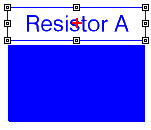
Drag a rectangle.
Your rectangle is created.

-
From the
Filled Shapes Properties section in the
Modelica Graphics Properties dialog box, select
the blue color from the
Fill Color option.
-
Define the
Fill Style option as
Solid.
The rectangle is filled with blue.

-
From the
Diagram section of the
action bar,
click
Text
 . .
The
Text Properties section of the
Modelica Graphics Properties dialog box is
expanded.
-
Drag the bounding box of the text.
The text is created, with the text that
is present in the
Content box from the
Text Properties section of the
Modelica Graphics Properties dialog box.
-
Change the text in the
Content box to the text you want.
The text is changed.

-
Select the font size of the text from the
Font size box from the
Text Properties section of the
Modelica Graphics Properties dialog box.
The default value
auto means that the text font size by default
adapts to the size of the bounding box.
-
Draw three ellipses the following way:
-
From the
Diagram section of the
action bar,
click
Ellipse
 and draw it
the same way as the rectangle. and draw it
the same way as the rectangle.
-
From the
Filled Shapes Properties section in the
Modelica Graphics Properties dialog box,
select from the options to get as result a solid dark line color with double
line thickness and a solid light fill color.
-
From the
Ellipse Properties section, change
End Angle to 300 and select
Closure to
None.
-
Select the ellipse and use
Ctrl+C and
Ctrl+V to copy and paste it.
-
For the new ellipse, from the
Ellipse Properties section, select
Closure to
Chord.
-
Copy and paste like above to create a third ellipse.
-
For the third ellipse, from the
Ellipse Properties section, select
Closure to
Radial.
The result is:

-
Minimize the
Modelica Graphics Properties dialog box.
Modelica Graphics Properties icon
appears on the right side of the screen.
-
If you need to modify:
- One component:
Select the component, the
Modelica Graphics Properties dialog box appears.
- Several
components: Multiselect components, then click
Modelica Graphics Properties
 . .
|