Before You Begin
Before starting the app,
make sure that the Persist Resource Position check box is
selected. This option is available in
.
Note:
The app performance may vary depending on the type of part used. Do not use parts
containing lattices.
About the Help Icon
The Help icon is available in most dialog boxes. It
displays visual representations of the various parameters available.
From any dialog box, click Help
 to display a 3D
representation of the parameters available in the work area. to display a 3D
representation of the parameters available in the work area.
Machine Customization
You can import a DLL file to associate it with the machine in session and display
a list of services. You can also create a virtual machine based on DLL files provided
by machine vendors.
Native Services or Virtual Machine Services
You can import a DLL file to associate it with the machine in session. You can
then display a list of services that you can add to or override the native
services of the application. You can choose between using native or virtual
machine services. The services available are as follows:
- Add or edit rules.
- Best orientation computation: Specify an orientation in which to print a
given part.
- Nesting computation: Position
the parts to print in the build envelope of the machine for a given set
of parts and number of instances required.
Note:
You can show the build envelope as a cube surrounding a machine
with Hide/Show Build Envelope
 in the Setup section of the action bar. in the Setup section of the action bar.
Specify the value of the build envelope in the
Rectangular Build Envelope section of
the Reference Parameters dialog box.
- Scan path generation: Compute
and order the scan path for a set of parts (and their supports) inside
the build volume of the machine.
- Post processor services:
Translate the geometry, slices, or scan path into a file that you can
send to the machine to start the print.
Before importing the DLL file, you must create a reference DLL file implementing
the following API:
int ComputeScanPathInAZone(const char* iParamsAsXML, const Object* iSlice,
	                    Object *& oScanPath)
A file containing the API is available in
<V6_install_dir>\startup\Additive\ExternalServices.h.
The table below lists the parameters to define in the reference DLL file:
| Parameter |
Description |
iParamsAsXML
|
Input parameter that corresponds to the
XML content. The content describes the parameters to use for
computation. |
iSlice
|
Input parameter that corresponds to the
C-structure. The structure contains the geometry of the zone
where to generate the scan path and other parameters.
|
oScanPath
|
Output parameter that corresponds to the
structure containing the generated path. |
Virtual Machine
You can create a virtual machine based on DLL files provided by machine vendors.
The services available are as follows:
- Best orientation computation: Specify an orientation in which to print a
given part.
- Nesting computation: Position the parts to print in the build envelope
of the machine for a given set of parts and number of instances
required.
- Scan path generation: Compute and order the scan path for a set of parts
(and their supports) inside the build volume of the machine.
- Post processor services: Translate the geometry, slices, or scan path
into a file that you can send to the machine to start the print.
You can also associate a configuration file to virtual machines. Click a
configuration file from the Configuration File list under
the Services
tab in the Reference Parameters dialog box. You can edit the
files available in the Configuration File list under .
Note:
Configuration files may be required to connect the virtual machine to a
third-party software.
Managing Machine Vendor Rules
When creating rules with the virtual machine, you can update the list of rules
declared on the machine using the associated machine vendor DLL files. Click
Update List of Rules under the
Rules
tab in the Reference Parameters dialog box.
Note:
Rules that come from machine vendor DLL files are considered external
rules. You cannot add or remove external rules defined on the virtual
machine. You can only browse and partially edit them. Some native services
may no longer be available when external rules are applied.
Scanning Optics Definition
You can define scanning optics to manage lasers during the printing simulation
process. You can give each parameter an associated Name
and ID, which appears in the Scanning
Optics dialog box.
Trajectories generated by the scan path computation are optimized based on each
laser's parameters and position. These new trajectories are stated in the output
files.
- Scanning Optics Parameters
- The following parameters are available:
| Parameter |
Description |
| Max Scan
Speed
|
Specifies the maximum scanning
speed. By default, the value is 10m/s. |
| Max Scan
Power
|
Specifies the maximum scanning
power. By default, the value is 600W. |
| Max Jump
Speed
|
Specifies the maximum jump speed.
By default, the value is 10m/s. |
- Beam Parameters
-
The following Beam parameters are available:
| Parameter |
Description |
| Focal
Diameter
|
Specifies the beam focal
diameter. By default, the value is 0.2mm. |
| Maximal Defocusing
Length
|
Specifies the maximum
defocusing length. By default, the value is 0.1mm.
|
- Scope Parameters
- Depending on the Shape Type selected (rectangle
or circle), the following parameters are available:
-
| Rectangle |
Circle |
|
| Parameter |
Description |
| Length
|
By default, the value is the
difference between the minimum and maximum Y
value. |
| Width
|
By default, the value is the
difference between the minimum and maximum X
value. |
|
| Parameter |
Description |
| Radius
|
By default, the value is:
150mm. |
|
- You can edit these parameters directly in the work area.
- Mirror Mounting Point Parameters
- You can also define the Mirror Mounting Point
using the X, Y, and Z coordinates. This is in the top center of the
build envelop by default.
Chamber
You can define chamber parameters to specify parameters for the additive
machine.
| Parameter |
Description |
| Gas Inlet Direction
|
Direction of the gas. By default, the value is
along the x-axis (value = 0). |
| Gas Inlet Distribution
Type
|
Distribution of the gas in the build chamber:
lateral or from center to border. |
| Gas Inlet Area |
Area of the entrance of the gas in the build
chamber. |
Exclusion Zones
Exclusion zones are zones on the build tray or on a part that are designated as zones
free of machining. Zones defined as exclusions zones remain in the database while
saving data and can be associated to a rule.
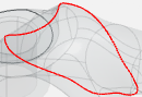
You can define exclusion zones on a part using the Edit Exclusion
Zones
 command
from the Build Layout dialog box. This command opens the
exclusion zone panel and displays the exclusion zone context toolbar. command
from the Build Layout dialog box. This command opens the
exclusion zone panel and displays the exclusion zone context toolbar.
The exclusion zone panel contains a list of current exclusion zones.
The exclusion zone context toolbar allows you to free-form draw or generate a predefined shape as an exclusion zone.
When a new exclusion zone shape is created using the context toolbar, it appears on the build tray and is projected along the z axis up to the maximum
height of the machine to create a solid body. You can use the Robot to edit the shape and its placement on the build tray.
For more information, see Commands Accessible from Exclusion Zone Creation and Positioning the Parts on the Build Tray.
Regions
Regions are volumes that you can define on a part. It is useful to define regions if
you plan to generate a different slicing and scan path on specific volumes of a
part.
To create a region, you must select a closed volume that corresponds to a physical
product. It is only possible to define regions if the part contains two or more
physical products.
For more information, see Adding Regions.
Scan Path
You can generate a scan path for laser or electron beam fusion methods. It is
possible to generate several scan paths for the same part.
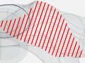
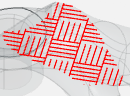
You can choose between the following types of scan path:
| Contouring |
Hatching |
Stripe |
Chessboard |
|
|
|
|
The difference between the Hatching and Stripe scan paths depends on the direction of
the path progression, identified by the blue arrow below:
| Hatching |
Stripe |

|

|
Rule Parameters
Depending on the scan path selected, the following parameters are available in
the Global Parameters, Compose
Strategy, and Scan Path Order
tabs:
- Global Parameters
-
The Global Parameters
tab lets you detect slicing, upskin, and downskin.
- Scan Path Rule: Name of the scan path rule.
- Slicing step: Specifies how the part is cut along
the z axis. By default, the value is 0.1mm.
-
| Downskin |
Upskin |
|
| Parameter |
Description |
| Minimal Skin
Width
|
The specific value that a
surface is considered downskin. By default, the
value is 1mm. |
| Number of
Layers
|
The specific number of
downskin layers. By default, the value is
1. |
| Restrict Core by
Downskin
|
If set to
True, the scan path for the
core does not overlap the scan path for downskin.
|
|
| Parameter |
Description |
| Minimal Skin
Width
|
The specific value that a
surface is considered upskin. By default, the
value is 1mm. |
| Number of
Layers
|
The specific number of
upskin layers. By default, the value is 1. |
| Restrict Core by
Upskin
|
If set to
True, the scan path for the
core does not overlap the scan path for upskin.
|
|
- Compose Strategy
- The Compose Strategy
tab contains the scan path definitions in each zone of application: Core,
Downskin, and Upskin.
- Zones Type: Core,
Downskin, and
Upskin.
| Contouring |
In Fill |
|
| Parameter |
Description |
| Depth
|
Orders the definitions from
the most external one to the most internal one
inside a zone. |
| Definition
|
Name of the
definition. |
| Periodicity
|
Specifies the frequency of the scan path to apply
to the slices. By default, the value is 1
(integer).
|
| Start
|
Index of the first slice from which the
definition is applied. |
| Range
|
Specifies a number of slices
on which the scan path definition applies.
|
| Action |
Action available on the definition. You can
edit  or delete or delete  the definition. the definition. |
|
| Parameter |
Description |
| Depth
|
Orders the definitions from
the most external one to the most internal one
inside a zone. |
| Definition
|
Name of the
definition. |
| Periodicity
|
Specifies the frequency of the scan path to
apply to the slices. By default, the value is 1
(integer).
|
| Start
|
Index of the first slice from which the
definition is applied. |
| Range
|
Specifies a number of slices
on which the scan path definition applies.
|
| Action |
Action available on the definition. You can
edit or delete the definition. |
|
- Definition Parameters
- Scanning Rule: Lists the existing scanning rules
that you can link to the scan path definition inside the scan path
rules. You can create a new scanning rule here if a rule does not
already exist.
- Contouring:
| Contouring XY Strategy |
Contouring Z Strategy |
|
| Parameter |
Description |
| Number contouring
pass
|
Specifies the number of
contouring passes to create. |
| Radial
step
|
Specifies the space between two consecutive
paths of the same scan path. By default, the value
is 0.1mm.
|
| Offset from last
contouring
|
Specifies the space between
the last contouring pass of the previous scan path
and the current scan path. By default, the value
is 0mm. |
| Random starting
point
|
Starts the scan path at a random point of
the contouring trajectory. |
| From inner to
outer passes
|
If more than one contouring
pass is defined, start the scan path from the
inner pass to the outer one. |
|
| Parameter |
Description |
| Periodicity
|
Specifies the frequency of the scan path to
apply to the slices. By default, the value is 1
(integer).
|
| Apply on a Range
of Slice
|
Applies the scan path
definition to a certain number of slices. By
default, the definition applies to all the slices
starting from the value specified for the
Starting slice
parameter. |
| Starting
Slice
|
Specifies a number of slices
on which the scan path definition applies.
|
| Range of
Slice
|
Specifies a number of slices
on which the scan path definition applies. |
|
- In Fill
| Hatching |
Stripe |
Chessboard |
|
| Parameter |
Description |
| Infill
mode
|
Specifies the scan path
mode, such as back and forth, or one way. |
| Angle rotation
between slices
|
Specifies a rotation angle
between a given slice and the previous or next
one. This is useful to alternate the direction of
hatching for example . |
| Hatching
Direction
|
Direction of the hatch
pattern when applied for the first time. By
default, the value is 0. |
| Radial
step
|
Specifies the space between
two consecutive paths of the same scan path. By
default, the value is 0.1mm. |
| Offset from last
contouring
|
Specifies the space between
the last contouring pass of the previous scan path
and the current scan path. By default, the value
is 0mm. |
|
| Parameter |
Description |
| Infill
mode
|
Specifies the scan path
mode, such as back and forth, or one way. |
| Angle rotation
between slices
|
Specifies a rotation angle
between a given slice and the previous or next
one. This is useful to alternate the direction of
hatching for example . |
| Stripe angle to
Hatching direction
|
Angle of the stripe toward
the hatching direction. By default, the value is
90 degrees. |
| Hatching
Direction
|
Direction of the hatch
pattern when applied for the first time. By
default, the value is 0. |
| Stripe
width
|
Distance between two
consecutive red dotted lines. |
| Radial
step
|
Specifies the space between
two consecutive paths of the same scan path. By
default, the value is 0.1mm. |
| Offset from last
contouring
|
Specifies the space between the last contouring
pass of the previous scan path and the current
scan path. By default, the value is 0mm.
|
|
| Parameter |
Description |
| Infill
mode
|
Specifies the scan path
mode, such as back and forth, or one way. |
| Angle rotation
between slices
|
Specifies a rotation angle
between a given slice and the previous or next
one. This is useful to alternate the direction of
hatching for example . |
| Stripe angle to
Hatching direction
|
Angle of the stripe toward
the hatching direction. By default, the value is
90 degrees. |
| Hatching
Direction
|
Direction of the hatch
pattern when applied for the first time. By
default, the value is 0. |
| Square
size
|
Length of the square.
|
| Radial
step
|
Specifies the space between
two consecutive paths of the same scan path. By
default, the value is 0.1mm. |
| Offset from last
contouring
|
Specifies the space between
the last contouring pass of the previous scan path
and the current scan path. By default, the value
is 0mm. |
|
- Scan Path Order
- The Scan Path Order
tab lets you modify the order of the scan paths.
Skin Surfaces
A skin surface is an area on a layer of a part, with no material above or
below.
There are several types of skin surfaces:
- Upskin: upward facing surface of a
part with no material above.
- Downskin: downward facing surface
of a part with no material below.
- Core: corresponds to the surface
between an upskin and downskin surface.

Skin surfaces are automatically detected on a part when you create a scan path rule
in the Scan Path Definition Sequence
tab.
You can generate a scan path on any type of skin surface using the general scan path
parameters, and order them in a sequence. For more information, see Scan Path.
For each surface, the following colored scan paths are generated:
- Red for core surfaces
- Yellow for downskin surfaces
- Green for upskin surfaces
Note:
The parts and supports are not highlighted.
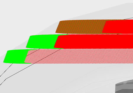
Scan paths with different definitions might overlap each other. In this case, only one color
is displayed. Zoom-in on the colored scan path to check that the color displayed
corresponds to one scan path only.
The following skin surfaces parameters are available:
| Parameter |
Description |
| Minimal Skin Width
|
The specific value that a surface is considered
upskin or downskin. By default, the value is 0.1mm. |
| Number of Layers
|
The specific number of upskin or downskin layers.
|
| Restrict Core by Downskin
|
If set to True, the scan
path for the core does not overlap the scan path for downskin or
upskin. |
Scan Path Analysis
You can do an analysis to compare the trajectory of the scan path with the design of
the part.
- Geometrical Parameters
-
| Slices
|
Part Display With
Transparency
|
Error Detection
Range
|
|
| Parameter |
Description |
| Bottom
|
Specifies the bottom slice
width. |
| Top
|
Specifies the top slice
width. |
|
| Parameter |
Description |
| Design
Part
|
Specifies the visibility and
transparency of the design part. |
| Manufactured
part
|
Specifies the visibility and
transparency of the manufactured part. |
|
| Parameter |
Description |
| Low-Melting
Detection
|
Specifies the value for a
low-melting error point. |
| Roughness
Detection
|
Specifies the value for a
roughness (extra material) error point. |
|
- Section
Specifies sectioning on the part to see inside of the part for each
slice.
- Physical Parameters
- Activate Physical Analysis
-
| Powder |
Chamber |
|
| Parameter |
Description |
| Density
|
Specifies the density of the
powder. |
| Melting
Point
|
Specifies the melting point
of the powder. |
| Porosity
|
Specifies the porosity of
the powder. |
| Absorption
Coefficient
|
Specifies the amount of
energy that the powder can absorb. |
| Diffusivity
|
Specifies the amount of
energy that the powder diffuses. |
| Conductivity
|
Specifies the conductivity
of the powder. |
| Specific Heat
Capacity
|
Specifies the heat capacity
of the powder. |
|
| Parameter |
Description |
| Preheat
Temperature
|
Specifies the preheat
temperature. |
| Pending Time
Before Scanning
|
Specifies the time allotted
for the piece to cool off between passes.
Note:
This parameter includes new powder level
deposition time.
|
|
Supports
Supports stabilize the part during the build process, and reduce residual stress by
improving thermal diffusion during the build. You can select multiple supports at
once using Ctrl and clicking the required supports.
For more information, see Rules for Generating Supports.
Supported Parts
Only STL parts with closed volumes are compliant with the app.
However, if you load an STL part with closed volumes, it is not possible to:
- Compute the orientation of a part
that minimizes the volume of supports.
- Automatically positions the parts on the build
tray using Generate Nesting
 . .
Output
You can generate a file containing geometrical and slicing information.
Export Parameters
The following methods are available:
| Method |
Description |
| Geometry without support
structure
|
Exports the geometry with the support
structure. |
|
Geometry with support structure
|
Exports the geometry without the support
structure. |
| Only support
structure
|
Exports only the support structure.
|
Check Build
You can check the build setup by clicking Check Build in
the Generate Output dialog box. The resulting
information is displayed in the Messages Reporting dialog
box.
Generate Documentation
You can generate a shop floor documentation when exporting by selecting
Generate Documentation.
If the Save output(s) in Manufacturing Cell option is
activated, the documentation will be stored in the same NC container than the
output. If not, it will be stored at the same location than the output.
You can generate the documentation along with the output file for the selected position
parts. You can use either a default template or a customized template defined in .
See Customizing Preferences
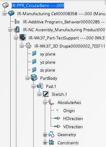
Tree Structure
The additive manufacturing process content is located under a manufacturing cell
in a PPR Context.
Below are examples of the typical structure and content that appear in the tree when working in the app.
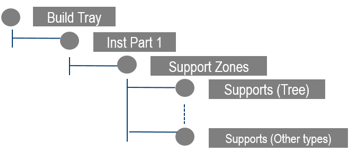
The manufacturing cell contains:
- A build tray node with elements
from your working environment.
- An instances node for the parts
positioned on the build tray and a context menu for instance part.
- A support zones node for each instance containing the support features
grouped based on their type of support.
- A support features node for each support zone grouped based on type.
In the tree, you can do the following:
- Multiselect objects and cross-highlight objects from the tree to the work area.
- Select objects in tree during the command scope.
- Sort the supports with a context menu on the build tray based on:
- If there are any supports for the zones, then all the zones with no
supports are grouped together.
- The types of the supports, which could be either edges, point, or
tree.
|
