Create the Operation
This procedure shows you how to create a Roughing operation using Prismatic Roughing command.
-
Activate the Manufacturing Program and click
Prismatic Roughing
 in the Prismatic Machining action bar.
A Prismatic Roughing entity is added to the Manufacturing Program.
in the Prismatic Machining action bar.
A Prismatic Roughing entity is added to the Manufacturing Program.The Prismatic Roughing dialog box appears directly at the Geometry tab
 .
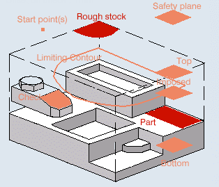
This tab includes a sensitive icon to
help you specify the
geometry.
By default, The areas of the icon are colored red indicating that this geometry is required.
- Still in the Geometry tab.
- Click the red Part area then select the part to machine in the 3DEXPERIENCE platform.
- Click the red stock
area in the icon then select the stock in the 3DEXPERIENCE platform.
The Part and stock are required. All other geometry is optional.
- Set Offset on part to 0.1mm.
- Select the Strategy
tab
 to set the machining parameters, radial and axial stepover conditions, HSM, and user parameters.
- If you have selected a Back and forth tool path style, click the arrow in the sensitive icon to modify the proposed tool axis direction, if necessary.
- If needed, click the tool axis symbol to invert the tool axis direction. See Defining the Tool Axis
- Go to the Tool tab
 to select a tool.
Only end mill tools is used in Prismatic Roughing operations.
- Select the Feeds and Speeds
tab
 to specify the feedrates
and spindle speeds for the operation.
 - Select the Macros tab
 to specify the operation NC Macros
(approach and retract motion, for example).
 -
Click Display or
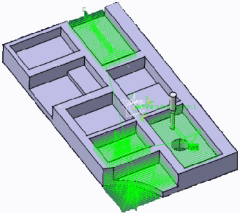
Simulate to check the validity of the operation.
- The tool path is computed.
- A progress indicator is displayed.
- You can cancel the tool path computation at any moment before 100% completion.

- Click OK to create the operation.