Standard Branch Points
A standard branch point is defined by its reference point and its position on the branch curve.
Reference Point
For standard branch points, the reference point can be a route element or another branch point that is part of the activated branch.
When creating or editing standard branch points, selecting Change Reference Object ![]() allows to select another reference point.
allows to select another reference point.
Positioning Standard Branch Points
To position a standard branch point, you can either work with distance, with ratio, or with the context of your design.
Using Distance
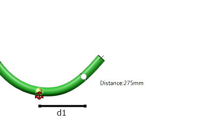
The distance is the branch length separating the branch point from its reference point (d1 in our example).
Clicking the Distance label enables to enter a precise value for the branch length. Others tools are also provided when you right-click the Distance box:
| Tools | Description |
|---|---|
| Measure Item and Measure Between | Allow to create measurements. For more information, see Part Design User's Guide: Measuring in the Part Design App. |
| Change Step | Allows to edit the increment of the
Distance box. The default step is 1mm but you can set as many steps as needed and retrieve them easily while using the Change step tool. |
| Range | Allows to edit the minimum and maximum branch length you
can set between a branch point and its reference point. Ranges can only be reduced. Out of range values are not taken into account. |
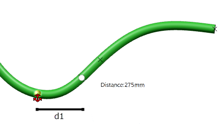
If you work with distance and edit the branch curve, the branch length (d1) remains the same. Therefore, even if the curve is edited, the branch point remains at the same position on the curve.
| Before Edition | After Edition |
|---|---|
 |
 |
Using Ratio
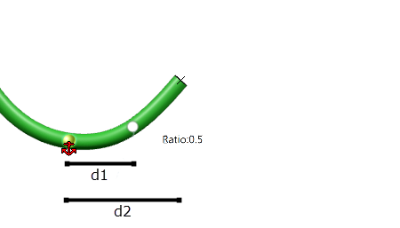
The ratio is the relation between the branch length separating the branch point from its reference point and the branch length between the reference point and the segment's end (d1 / d2 in our example).
0 is the value for the reference point and 1 is the value for the segment's end.
If you work with ratio and edit the branch curve, the ratio remains the same. However, as the ratio represents a percentage, the position of the branch point is updated according to the new relation (d1' / d2').
| Before Edition | After Edition |
|---|---|
 |
 |
| Tip:
Clicking Change Branch Point Unit
|
Using Contextual Features
Geometrical elements that are part of your product can be used to position a standard branch point on the curve. The following elements can be used as contextual features:
- Vertex
- Point
- Plane
- Face
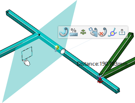
When you hover over a geometrical element (during creation or edition of a branch point), a visual feedback is provided if there is a valid intersection with the curve of the branch:
| Plane Used as Contextual Feature | Point Used as Contextual Feature |
|---|---|
 |
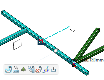 |
After clicking the eligible element, a ruler appears to let you define an offset between the intersection and the branch point position.
- For an intersection with a plane, the ruler's direction is normal to the plane.
- For an intersection with a point, the ruler's direction is tangent to the curve.
| Ruler for a Plane | Ruler for a Point |
|---|---|
 |
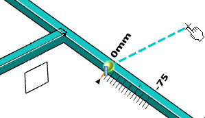 |
| Important: There is no associativity between the standard branch point and the geometrical element used to define its position. Editing the selected contextual feature after positioning the branch point has no impact on the branch point's position. |

 Primary network;
  Secondary networks;
  Proxy branch points.