You can remove and fill features like holes, pockets, or other
openings using the
Functional Import Wizard.
The wizard associates the functional behavior of protected, added, and
removed features to these openings. This allows you to use the input part
smoothly with the
Functional Plastic Partsapp.
The
Functional Import Wizard consists of three steps:
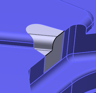
Defining the faces required to compute the openings within the part.
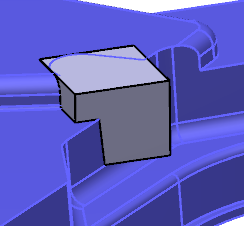
Computing and filling the openings in the part.
Generation of the new functions.
Note:
Depending on your role, you
may not have access to this functionality.
Before you begin: Open the input part that is essentially a thin part, consisting of
a distinct parting element. This parting element divides the part into an inner
surface (core), an outer surface (cavity), and the parting element itself.
Define Faces
In the face selection step, you can define the face required
to compute the openings within the part.
From the
Structure section of the
action bar,
select
Functional Import Wizard.
The
Functional Import Wizard dialog box appears.
The input part with opening (circled)
In the
Shell Faces area:
Select the
Shell Parting Faces.
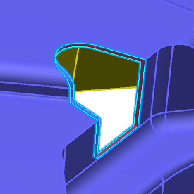
Shell faces are in contact with the parting element. They
divide the part into inner and outer faces respectively.
The selected faces are highlighted in pink.
The
Compute Parting Element option is
available for selection.
Select the
Parting Element, if known. You can also
select the
Compute Parting Element option, to
select the parting element automatically.
Parting element is the one that supports the shell faces.
The parting element is selected. An arrow defining
the area to be kept is displayed.
Note:
The
Compute Parting Element option can be
used in most general cases.
In the
Inner Faces area:
Select the
Inner Faces.
The selection is done by tangent propagation.
Note:
Select all the faces limiting the inner region of the
part except the holes, pockets, or other openings which need to be filled.
The selected faces are highlighted in yellow.
To select fillets with certain range of radius, select the
Inner Radius option and define the range
of
Fillet Radius Range.
This is needed when the selection extends along a filleted
face of an opening. This helps to stop the tangent propagation from the face to
the opening.
In the
Outer Faces area:
Select the
Outer Faces.
The selection is done by tangent propagation.
Note:
Select all the faces limiting the outer region of the
part except the holes, pockets, or other openings which need to be filled.
The selected faces are highlighted in blue.
To select fillets with certain range of radius, select the
Outer Radius option and define the range
of
Fillet Radius Range.
This is needed when the selection extends along a filleted
face of an opening. This helps to stop the tangent propagation from the face to
the opening .
Using the object bag
, you can select several faces and clear the faces that are
not required.
 .
The Functional Import Wizard dialog box appears.
.
The Functional Import Wizard dialog box appears.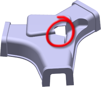
 , you can select several faces and clear the faces that are
not required.
The Next button is now available.
, you can select several faces and clear the faces that are
not required.
The Next button is now available.