Configuration of View Generation Modes
You can configure the view generation modes through
expander.
In this case, it is used while creating new views. For more information, see View. Once a view has been created, you can modify its properties through the
Properties dialog box. Right-click the view, select
Properties, click the Generation tab, and
then select the required options. For more information, see Generation Properties.
Exact View
Exact views are generated from the design mode, that is, they are the views for
which the geometry is available. The exact generation mode is the best option in most of the
cases, because of the following features:
- This is the most accurate view generation mode.
- All types of views can be generated using this mode.
- Functionalities like dress-up, dimensions, annotations, are available.
- You can generate them in shaded background mode. That is you can create exact views with
visualization of a raster view.
- Polyhedral data integration: Any kind of data from any exotic or regular CAD source (for example, polyhedral V4 .model data) are supported.
Note:
The edges of faces with a relative angle of less than 0.5 degrees are considered as being
smooth edges, and therefore are not represented.
However, there are a few cases for which choosing the exact generation mode is not be
appropriate:
- In the case of sophisticated products or assemblies involving large amounts
of data, generating exact views may consume too much memory.
- The edges of faces with a relative angle of less than 0.5 degrees are considered as being smooth
edges, and therefore are not represented.
Clash DetectionClashes correspond to the collisions between two parts in an assembly or two bodies in a part.
Clashing bodies may be incorrectly projected in exact projection and section views: some edges of these bodies may appear whereas they must be
hidden, or may disappear whereas they must not be hidden.
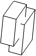
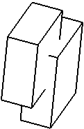
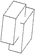
The image below shows clashing bodies in a 3D representation: 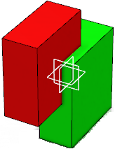 Using Clash detection option in Exact view identifies the location of the
clash and gives a correct projection of the clashing bodies. When you select this option,
the edges that are intersecting with other surfaces or volumes are split at the
intersection point, and each of the parts of the edges are correctly projected. The following table depicts this scenario in each of the view modes: | View Mode | Visual Representation |
|---|
| CGR |
| | Approximate |
| | Raster |
| | Exact | With Clash detection option cleared:
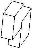
| With Clash detection option selected:
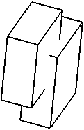
|
To avoid such clashes and ensure that the edge representing the border of the collision is
projected, you can modify the assembly or part using either of the following methods: - Move the parts or bodies in such a way that the clash is avoided.
- If possible, use Boolean operations (such as Add,
Remove, Intersect,
Assemble, and Union Trim in Part Design)
to generate a single body resulting from the intersection.
To ensure that a screw in a threaded hole is not considered as a clash in a section view or a breakout view, you must design the screw as a whole 3D part representation, apply a thread feature to the screw, and create the hole as a threaded hole (see Part Design User's Guide: Creating threaded holes). Then, on the part instance associated to the screw, you must perform either of the following: Shaded Background ModeYou can generate an exact view in the shaded background mode. That is, you can create an exact view with the visualization of a raster view. This gives the look and feel of the 3D representation to the view. The view is an image of 3D geometry, or the raster view, with the capabilities of an exact view. You can customize the preferences for the shading background mode in the View
Generation section of the
> View expander. For more
information, see View Generation. In this mode, you can do the following: - Create the views of the 3D representation with the generated items including front view, isometric view, projection view, auxiliary view, unfolded view, view from 3D, section views and cuts, detailed views, and clipping views.
- Hide or show the shaded background image on the view after the image is generated on the view.
- Apply operators on the view to create breakout views, broken views, and 3D clippings.
- Apply hatching and pattern to the sections. You can select the color for the hatching and dotting patterns. For color and image pattern, the selected color has no effect.
You can either generate views in the shaded background mode or you can also create views and then
apply the shaded background image on them. To do so, right-click a view and select
Properties. In the Generation tab, under
the Generation Mode section, select the Shaded
Background Mode check box. This is available for selection only for an exact
view.
- Shaded Background Mode
- When you select this check box, in Generation Mode Options
dialog box, under Shaded Background Mode Options, click
Options, and you can customize the following options:
- Mode: You can create views with
Shading or with Shading, no light
source. There can be a minor difference in the shading of the view
because of the light source. You can select the With
texture check box to represent the texture of the part in the
view.
- Level of detail (DPI): You can select the level of
detail for the visualization mode and the print mode. There are four levels of
detail for each mode:
| Level of detail |
Default value for visualization and for
print |
Editable values? (Yes or No) |
| Low quality |
36.29 |
No |
| Normal quality |
145.14 |
No |
| High quality |
580.57 |
No |
| Customize |
145 |
Yes |
In the Hatching/Dotting Pattern Background for Operators
area, you can customize the hatching or dotting pattern for background operators
such as section views or cuts, callouts, details, and breakout operators.
- Select Color from 3D to inherit the hatching or
dotting pattern as defined on the 3D part. By default, this is selected.
- Select Color from Palette to select the required
color from the palette.
You can select the color for the hatching and dotting patterns. For fill
color and image pattern, the selected color has no effect.
Note:
If you generate a view in background shaded mode from a 3D representation,
which has material applied to it, and then you change the material, you must manually
update the drawing sheet to update the modifications.
Approximate View
Approximate views are generated using the Approximate mode. Although
Approximate views are not as high in precision and quality as exact views, this generation
mode dramatically reduces memory consumption. The performance can also be improved,
depending on how you fine-tune the precision. Therefore, the Approximate mode is
particularly well adapted to sophisticated products or assemblies involving large amounts of
data.
3D wireframe geometry can be projected in Approximate views. In the case of projection of 3D wireframe geometry, the only option applicable is Can
be hidden which is available through:
-
expander, under Geometry generation/Dress-up,
select the Project 3D wireframe option, and click
Configure.
- Right-click the view and select Properties. In the
Generation tab, under Dress-up, select
the 3D Wireframe check box.
Polyhedral elements (such as surfaces or wireframes) from V4 .model documents are supported. The Approximate mode offers about the same advantages and restrictions like
the CGR generation mode (see About the View Generation Modes). However, there are some differences:
- Approximate consumes even less memory than CGR.
- Approximate is faster than CGR, but performance largely depends on fine-tuning.
- Approximate provides more approximate results than CGR, but these results
largely depend on how you fine-tune the precision.
- Approximate lets you generate section views, section cuts, and breakout views. However, certain restrictions apply, which are
documented in other parts of this user's guide, when appropriate.
For more information about the advantages and restrictions associated with
the Approximate generation mode, see
Advantages and Restrictions Common to CGR and Approximate below.
Raster View
Raster views are generated as images. This enables you to quickly generate
overall views for large products or assemblies, regardless of the drawing quality.
Such views are associative to the 3D geometry and can be updated when the part
or product changes.
Restrictions
Raster views involve a number of restrictions:
- You cannot generate the following types of views using this option: view
from 3D, section views, section cuts, detail views, breakout views, unfolded
views.
- Raster views cannot contain dress-up elements (axis, centerlines, threads).
- Creating dimensions is impossible.
- Generally speaking, all commands requiring the selection of geometry
are not available.
- Raster views cannot be edited (you can work around this by isolating the view:
double-clicking the image to start the image editor). However, the views generated in
raster mode can be rotated.
As a consequence of these restrictions, selecting this option disables a number of other
options in the View and in the Generation
tab (available through
) or in the Properties dialog box.
Overloading Colors/Graphic Properties
When the color of a product instance is overloaded at the product level, this color is
applied in the raster view to the elements contained in this product (including edges,
faces, points, and lines).
When other graphic properties are overloaded at the product level, they
are lost in the raster view (contrary to an exact view).
CGR View
CGR views are generated using the CGR format (CATIA Graphical Representation) of the 3D geometry.
A CGR format only contains a graphical representation of the geometry, which
is available with the Visualization mode (as opposed to the exact geometry,
which is available with the Design mode). The CGR view uses and displays only
the external appearance of the component and the geometry is not available. The
corresponding .cgr file, if it exists, is inserted from the cache system.
To generate a correct CGR view from an assembly composed of .cgr files, use only the
high-quality .cgr files, containing data about edges and faces. For example, a .cgr file
created with DMU Optimizer misses this information (to be as light as possible). In this
particular case, the CGR view mode can produce unpredictable results.
CGR views are not as high in quality as exact views, but they consume much
less memory during the generation. This may be useful when dealing with sophisticated
products or assemblies involving large amounts of data. However, this generation
mode is rather slow.
For more information about the advantages and restrictions associated with
the CGR generation mode, see
Advantages and Restrictions Common to CGR and Approximate.
Advantages and Restrictions Common to CGR and Approximate
Using CGR or Approximate to generate views offers the following advantages:
- Optimize memory consumption when generating and handling projection views
for large products or assemblies.
- Generate views from third-party data (such as Multi-CAD), as well as from polyhedral
elements (such as dittos or surfaces) in V4 .model documents. Be careful in using only the
high-quality .cgr files, containing data about edges and faces. For example, a .cgr file
created with DMU Optimizer misses this information (to be as light as possible). In this
particular case, the CGR and Approximate view modes can produce unpredictable
results.
However, the CGR or Approximate generation mode involves a number of restrictions:
- You cannot generate the following types of views:
- For CGR: section views, section cuts, detail views, detail view profile,
breakout views, unfolded views and views from 3D.
- For Approximate: detail views, detail view profile, unfolded views
and views from 3D.
- The following types of elements are not associative on CGR or Approximate
views:
- For CGR: Auxiliary view profiles, annotations, and
dimensions.
- For Approximate: Auxiliary view profiles, and annotations. Dimensions can be
associative, depending on whether you select the Allow the creation of
associative dimension in approximate views option in the
Dimensions associativity. See Dimension.
- You cannot project 3D elements such as wireframe or points. on CGR or Approximate
views.
- CGR or Approximate views cannot contain dress-up elements (axis, centerlines,
threads).
- Persistence of editing the graphical properties (color, line type, line thickness, no
show) and delete operations performed on generated elements are not available on CGR views
but available on approximate views. However, as approximate views are based on the 3D
representation (instead of the 3D topology for Exact Views) the associativity is limited. Therefore, if you modify a subpart
of your 3D design, then the corresponding 2D representation loses any graphical changes
that may have been made on it.
-
CGR or Approximate views being only a graphical representation
of the geometry, only line segments are generated in such views. In case
of non-associative dimensions (as is always the case for CGR views, and may
be the case for Approximate views when the Allow the creation of associative
dimension in approximate views check box is not selected), the only elements
that can be dimensioned are these line segments.
As a result, you may not be able create certain types of radius or diameter
dimensions in such views.
-
CGR or the Approximate option disables a
number of other options on the View and on the
Generation tab (available through
> Drafting) or right-click the view and select
Properties.
- Approximate items cannot be selected using the mouse (trap selection). However you can
click
 to select and edit the properties of a single item. Note that you can also multiselect
several items using the Ctrl key. to select and edit the properties of a single item. Note that you can also multiselect
several items using the Ctrl key.
-
Approximate items cannot be duplicated. The Duplicate
command is not available using context menu on an approximate item.
- Approximate items cannot be searched using the Find command. They cannot
be filtered by their graphical properties such as, linetype, color, or thickness.
- The mesh thickness has an impact on the CGR and approximate view performance. Moreover,
a CGR view cannot be computed from an extremely thin mesh, that is, when the mesh on a
single face consists of more than 6500 triangles. In this special case, you must raise the
3D accuracy (through
section, under 3D Accuracy) before projecting a CGR
view.
As a consequence of these restrictions, selecting either the CGR or
the Approximate option disables a number of other options on the
View and on the Generation tab (available
through
> Drafting) or right-click the view and select
Properties.
|


