Defining a Rebar Layer
You can specify one or multiple layers of reinforcement in membrane, shell, or surface elements. For each layer you specify the rebar properties including the rebar layer name; the cross-sectional area of each rebar; the rebar spacing in the plane of the membrane, shell, or surface element; the position of the rebars in the thickness direction (for shell elements only), measured from the midsurface of the shell (positive in the direction of the positive normal to the shell); the rebar material name; the initial angular orientation, in degrees, measured relative to the local 1-direction; and the isoparametric direction from which the rebar angle output will be measured.
You can model rebar layers in solid (continuum) elements by embedding a set of surface or membrane elements with rebar layers defined as discussed above in a set of host continuum elements.
Input File Usage
Use the following options to define one or more rebar layers in membrane elements:
MEMBRANE SECTION, ELSET=memb_set_name
REBAR LAYER
Use the following options to define one or more rebar layers in shell elements:
SHELL SECTION, ELSET=shell_set_name
REBAR LAYER
Use the following options to define one or more rebar layers in surface elements:
SURFACE SECTION, ELSET=surf_set_name
REBAR LAYER
Use the following option to model rebar layers in solid (continuum) elements:
EMBEDDED ELEMENT, HOST ELSET=solid_set_name
memb_set_name or surf_set_name
Assigning a Name to the Rebar Layer
You must assign each layer of rebar in a particular element or element set a separate name. This name can be used in defining rebar prestress and output requests.
Input File Usage
REBAR LAYER
rebar layer name
Specifying Rebar Geometry
The rebar geometry is always defined with respect to a local coordinate system. Defining an appropriate local system is described in the next section. The rebar geometry can be constant, vary as a function of radial position in a cylindrical coordinate system, or vary according to the tire “lift” equation. In each case you must specify the spacing, s, and the area, A, which are used to determine the thickness of the equivalent rebar layer, , as well as the angular orientation, , of the rebar with respect to this local system.
In addition, for shell elements you must specify the position of the rebars in the shell thickness direction measured from the midsurface of the shell (positive in the direction of the positive normal to the shell). If the shell's thickness is defined by nodal thicknesses (Nodal Thicknesses), this distance will be scaled by the ratio of the thickness defined by the nodal thickness to the thickness defined by the section definition. If the shell's thickness is defined with a distribution (Distribution Definition), this distance is scaled by the ratio of the element thickness defined by the distribution to the default thickness.
Defining Rebar with Constant Spacing
You can specify the geometry to be constant in the local rebar coordinate system. In this case the spacing, s, is specified as a length measure.
Input File Usage
REBAR LAYER, GEOMETRY=CONSTANT
Defining Rebar Spacing as a Function of Radial Position
You can specify the spacing, s, in terms of angular spacing in degrees as shown in Figure 1.
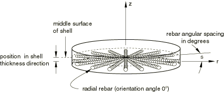
Angular spacing values can also be used for non-radial rebars as well as for rebars having nonzero orientation angles from the meridional plane. In these cases the orientation angles of the rebars do not change. The angular spacing option is used only to compute the spacing between rebars in units of length by multiplying the angular spacing by the radial distance of the concerned point on the rebar from the axis of axisymmetry. A local cylindrical coordinate system must be defined for the rebar if the rebar is associated with three-dimensional elements.
Input File Usage
REBAR LAYER, GEOMETRY=ANGULAR
Defining Rebar Using the Tire “Lift” Equation
Structural tire analysis is often performed using the cured tire geometry as the reference configuration for the finite element model. However, the cord geometry is more conveniently specified with respect to the “green,” or uncured, tire configuration. The tire lift equation provides mapping from the uncured geometry to the cured geometry (see Figure 2).
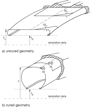
You can specify the spacing and orientation of the rebar cords with respect to the uncured configuration and let Abaqus map these properties to the reference configuration of the cured tire. Using a cylindrical coordinate system, the spacing, s, and angular orientation, , in the cured tire are obtained from
where r is the position of the rebar along the radial direction in the cured geometry, is the position of the rebar in the uncured geometry, is the spacing in the uncured geometry, is the angle measured with respect to the projected local 1-direction in the uncured geometry, and e is the cord extension ratio. In a tire e represents the pre-strain that occurs during the curing process; e =1 means a 100% extension. When is equal to 90°, the rebar is assumed to have a constant spacing of .
A local cylindrical coordinate system must be defined for the rebar if the rebar is associated with three-dimensional elements.
Input File Usage
REBAR LAYER, GEOMETRY=LIFT EQUATION
Local Rebar Orientation System
The rebar geometry, such as rebar orientation and spacing, is defined with respect to a local orientation system. This local rebar orientation system is entirely independent from the local orientation system used for the underlying assignment.
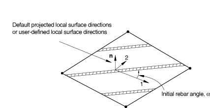
The rebar angle is always defined with respect to the local 1-direction as shown in Figure 3.
Rebar defined with either angular spacing or spacing defined by the tire lift equation is specified with respect to a cylindrical orientation system. For axisymmetric analysis the global coordinate system is used as the cylindrical system. For three-dimensional analysis you must provide a user-defined cylindrical orientation definition.
Local Orientation System for Three-Dimensional Elements
You can define the local system by referring to a user-defined local coordinate system. See Orientations for a description of how the local coordinate system is calculated from the user-defined directions for definition of rebar in shell, membrane, and surface elements.
If you do not specify a user-defined orientation, the local 1-direction is based on the default projected local coordinate system. See Conventions for a definition of the default projected local directions on a surface in space.
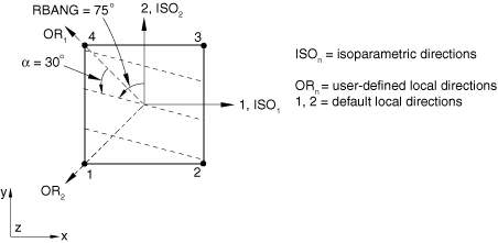
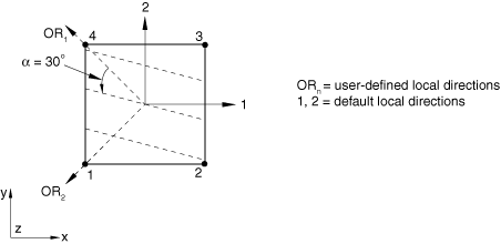
A positive angle defines a rotation from local direction 1 to local direction 2 around the element's normal direction or the user-defined normal direction. If the shell, membrane, or surface element is curved in space, the local 1-direction will vary across the element and the initial rebar angular orientation will also vary accordingly. The orientation definition that can optionally be associated with a shell or membrane section definition has no influence on the rebar angular orientation definitions. For example, in a membrane section, shell section, or surface section, the following data would result in the rebar layer definition shown in Figure 4: A=0.01; s=0.1; distance of rebar from the shell midsurface=0.0; =30.; and the rebar definition refers to a local rectangular orientation defined to have its X-axis go through the point (−0.7071, 0.7071, 0.0), its plane include the point (−0.7071, −0.7071, 0.0), and an additional rotation of 0.0 degrees about the 3-direction.
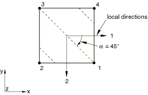
The following data would result in the rebar layer definition shown in Figure 5: A=0.01, s=0.1, distance of rebar from the shell midsurface=0.0, and =45.
Input File Usage
Use the following options to define the local 1-direction for a rebar layer:
ORIENTATION, NAME=name
REBAR LAYER, ORIENTATION=name
Local Orientation System for Axisymmetric Elements
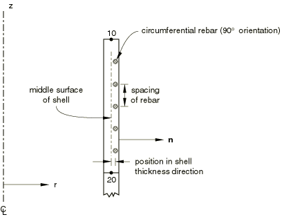
Rebars in an axisymmetric membrane element or an axisymmetric surface element must lie in the element reference surface, whereas rebars in an axisymmetric shell can lie in the shell reference surface or can be offset from the midsurface. Rebars in axisymmetric membrane, shell, and surface elements can be defined to have any angular orientation with respect to the r–z plane. See Figure 6 for an example of circumferential rebars and Figure 1 for an example of radial rebars in axisymmetric shells.
You cannot specify a user-defined orientation for rebar layers in axisymmetric membrane, shell, and surface elements. Instead, in the rebar layer definition you specify the angular orientation of the rebar layer, in degrees, with respect to the r–z plane; this orientation is measured positive about the positive normal to the membrane, shell, or surface element.
If you specify an orientation angle other than 0° or 90° for rebar in an axisymmetric membrane without twist, axisymmetric shell, or axisymmetric surface without twist, Abaqus assumes that the rebars are balanced (i.e., half the rebar lie at the specified angle and the other half at an angle of ) and internal calculations are handled accordingly. Such a rebar definition should not be used with the symmetric model generation capability (Symmetric Model Generation). The recommended modeling technique is to define unbalanced rebar in axisymmetric elements with twist. Balanced rebar, on the other hand, can be defined in regular axisymmetric elements or in axisymmetric elements with twist and should be defined by specifying half the rebar at the specified angle and the other half at an angle of .
Large-Displacement Considerations
In geometrically nonlinear analyses as the rebar-reinforced element deforms, the initially defined geometric properties and orientation of the rebar layer can change as a result of finite-strain effects. The deformation of the rebar layer is determined from the deformation gradient of the underlying shell, membrane, or surface element. Rebars rotate with the actual deformation and not with the average rigid body rotation of the material point in the underlying element. See Rebar modeling in shell, membrane, and surface elements for details.
For example, consider a plate modeled with a first-order element under large pure shear deformation as shown in Figure 7, where rebars are initially aligned with the element isoparametric directions.
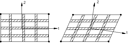
As a result of finite-strain effects, rebars rotate but remain aligned with the element isoparametric directions. If the same problem is modeled using anisotropic material properties rather than rebars and the material directions (1 and 2) are initially aligned with the element isoparametric directions, under such large shear deformation the material directions rotate and are no longer aligned with the element isoparametric directions. The material directions in this case are determined based on the average rigid body rotation of the material point. Hence, if the material is not truly a continuum, the anisotropic behavior is better modeled with rebars.