Introduction | ||
| ||
Problem Description
The two parts that will be assembled in this example are shown in the figure below. The clip is 51 mm long and 14 mm wide, and its three prongs are inserted into the buckle. The buckle is 37 mm long and 14 mm wide. The bottom face of the buckle is fully constrained, and the clip is free to move only in the z-direction. The clip and buckle are made of ABS plastic, which is assumed to be a linear elastic and isotropic material with a Young's modulus of 2 GPa, a Poisson's ratio of 0.394, and a density of 1020 kg/m3. The model is meshed with the default quadratic tetrahedral elements and a mesh size of 2 mm. The clip is inserted in the buckle by moving it –14 mm in the z-direction.

Workflow
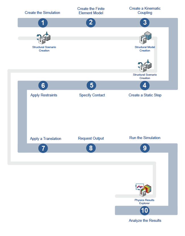
The workflow diagram below provides an overview of the example. The diagram shows the apps that you use as you perform the steps in sequence. Clicking a number in the diagram opens its corresponding step in the example.
| Task | Description | |
|---|---|---|
| 1 | Create the Simulation | Create the simulation by first importing the model into the 3DEXPERIENCE platform and then opening the model in the appropriate app. |
| 2 | Create the Finite Element Model | Use a finite element model (FEM) representation of your geometry to perform the simulation. |
| 3 | Create a Kinematic Coupling | Use a coupling to apply a load to represent pushing the clip into the buckle and to measure the insertion force. |
| 4 | Create a Static Step | Use a step to determine the nature and sequence of events in a simulation scenario. |
| 5 | Specify Contact | Specify contact interactions in your model to define the behavior of the simulated response when the selected surfaces come into contact. |
| 6 | Apply Restraints | Apply restraints to define the directions your model can and cannot move during the simulation. |
| 7 | Apply a Translation | Use an applied translation to specify the distance the clip is inserted into the buckle. |
| 8 | Request Output | Create an output request for the coupling. |
| 9 | Solve the Simulation | Run the simulation to solve for the insertion force. |
| 10 | Plot the Force vs. the Coupling Displacement | Display simulation data in a history plot with displacement as the independent variable. |
Complete the workflow steps in the order in which they are listed. Deviation from the instructions associated with each step might cause model or scenario errors, which might prevent convergence of the simulation.