Introduction | ||
| ||
Problem Description
Air ducts, like those found in construction and transportation industries, are typically redesigned many times before approval. Each time a new configuration emerges, computational fluid dynamics (CFD) engineers simulate the flow to determine the design's performance.
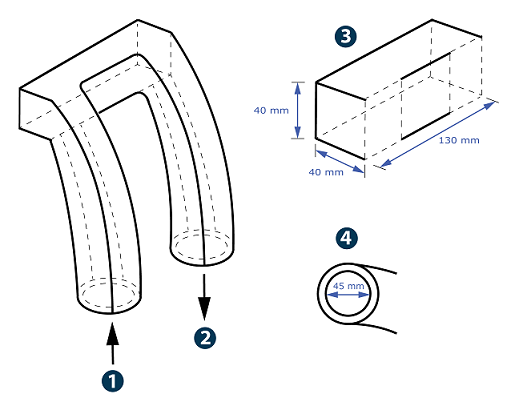
The duct model used in this example is an abstract shape in which air flows through one opening and out of the other, as shown in the diagram below.

![]() Inlet
Inlet
![]() Outlet
Outlet
![]() Detailed view of the midsection
Detailed view of the midsection
![]() Detailed view of an opening
Detailed view of an opening
The inlet air velocity is 5 m/s, and the outlet pressure is 0 N/m2.
This flow scenario is representative of a standard home appliance, like a clothes dryer, venting air through a duct to the air outside. To analyze the duct's performance, you will calculate the pressure drop and outlet flow velocity. You will also generate various types of plots to determine how to improve the original design.
Workflow
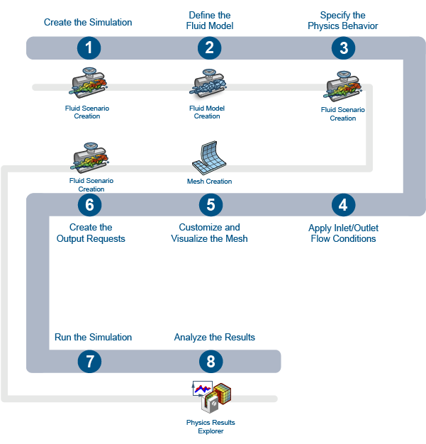
The workflow diagram below provides an overview of the example. The diagram shows the apps that you use as you perform the steps in sequence. Clicking a number in the diagram opens its corresponding step in the example.

| Task | Description | |
|---|---|---|
| 1 | Create the Simulation | Create the simulation by first importing the model into the 3DEXPERIENCE platform and then opening the model in the appropriate app. |
| 2 | Define the Fluid Model | Create the fluid domain, apply a material to it, and define the region where the flow occurs. |
| 3 | Specify the Physics Behavior | Specify the physics behavior of the fluid flow within the duct. |
| 4 | Apply Inlet/Outlet Flow Conditions | Apply flow conditions at the duct openings. |
| 5 | Customize and Visualize the Mesh | Use a finite element model (FEM) representation of your fluid domain to perform the simulation. |
| 6 | Create the Output Requests | Create the output requests to record data about pertinent variables. |
| 7 | Run the Simulation | Verify the steps for preparing the model, scenario, and mesh are complete and begin the simulation. |
| 8 | Analyze the Results | Analyze sensor readings and plots to understand the effects of the duct design on the airflow characteristics. |
You should complete the workflow steps in the order in which they are listed. Deviation from the instructions associated with each step might cause model or scenario errors, which might prevent convergence of the simulation.