Design a Road or Railway Earthwork
You can design a road or railway earthwork by using or creating typical cross sections, by adapting the cross section to an existing terrain.
-
From the Civil Engineering section of the action bar,
click Road Earthwork
 or
Railway Earthwork
or
Railway Earthwork
 to make a design
of a road or railway on a terrain.
to make a design
of a road or railway on a terrain.
The Road Stretch or Railway Stretch node is renamed. It appears in the tree and contains these features:
- Common Stretch: The terrain must be polyhedral. For more information, see Creating a Horizontal Alignment and Creating a Vertical Alignment.
- Filling Stretch: The geometry that is added on the ground.
- Excavation Stretch: The geometry that is removed from the
ground.
If you use the Road/Rail Subgrade Design command, you can add excavation and filling profiles in the subgrade cross section. For more information, see Creating or Splitting the Subgrade Layer of an Infrastructure.
-
Select a 3DEXPERIENCE road or railway surface feature, or any other
surfaces.
If you select a 3DEXPERIENCE road or railway surface feature, the alignment of the selected surface is automatically selected.
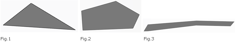
For other surfaces, it must contain 4 sides, based on the following criterion:
- If the angle between two consecutive edges of the surface boundary, projected on the XY plane, is less than 45 degrees, these two edges are considered as continuous.
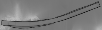
- The surface of Fig.1 contains only 3 sides, it is invalid.
- The surface of Fig.2 contains more than 5 sides, it is invalid.
- The surface of Fig.3, when it contains more than 4 edges, based on the above
criterion, it can be broken into 4 sides, and therefore become valid.
- Optional:
Select an alignment.
If the selected surface is a 3DEXPERIENCE road or railway surface feature, the alignment is displayed, its editor is disabled, and you cannot select another 3D alignment.
Otherwise, you can select any nonclosed curve, or an edge of the input surface as an alignment curve.
The input curve determines the road orientation, with its left and right sides based on road orientation. Here are specific cases about the selection of surface elements:
The start and end point of the input curve is on one side: 
When you select an edge of the input surface, the selected side is considered as the right side. The other sides are deduced automatically. The orientation of the input curve is ignored. There is one intersection point with one side, and another intersection point on the opposite side: 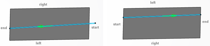
- Side, which is near to the curve start extremity is the start side.
There is only one intersection point with one side: 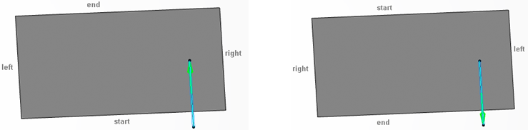
- The intersecting side is used as either the start or end side.
- If the start extremity of the input side is outside the surface (there is no projection of the curve start extremity on the surface in the Z direction) then it is the start side. Otherwise, it is end side.
There is no intersection: 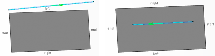
- In this case, the side that is most parallel to the input curve is used as the left or right side.
- The orientation of the input curve determines which is the right side.
The other sides are determined automatically.
There is an input curve, and it does not correspond to the above cases: - - The selected point must lie on the surface boundary.
- If the start element lies inside a side of the road surface, this side is used as the start side.
- If it is on the corner of two sides, then the shortest side is used as the start element.
The other sides are automatically determined, based on the general rule.
If the alignment curve is selected, you can select the start and end elements to limit the road design between them. The start and end elements must lie on the alignment curve.
If the alignment curve is not selected, you can only select a start point which must lie on the boundary of the input surface. You cannot select the end point.
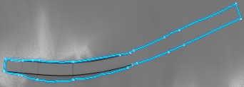
In the following case, the input curve is invalid, as shown in the figure below:
- A curve cannot intersect one side more than once.
- A curve cannot intersect more than two sides.
- A curve cannot intersect two consecutive sides.

-
Select the Object Type of a cross section by clicking Search an Object
Type in the Typical Cross Section field.
Only object types corresponding to the chosen discipline (which can be a platform, a road, or a railway) and undefined object types are visible. The content provided in the SubgradeTypicalCrossSections.3dxml stored in the
...\startup\Civil\Alignmentdirectory has been updated in R2022x GA to take the discipline into account.
To remove the cross section, click
 .
. The cross section can be based on an alignment sketch, or on a user-defined feature (UDF). If the object type contains two cross sections, one defined with the alignment sketch, the other with the UDF, the cross section defined with the alignment sketch is used.
If the cross section is UDF-based and has geometrical inputs named Base Surface or Base Alignment, the input surface of the earthwork is automatically assigned to the UDF input called Base Surface. The input alignment is automatically assigned to the UDF input called Base Alignment. You can change these inputs manually.
If the cross section is a UDF, an option Precision is added in the Parameters area of the Road Earthwork dialog box. Use one of the following computation modes:
- Coarse: To operate with user-defined cross sections only. This computation mode is quick but less precise.
- Medium: For a quick but less precise computation.
- Fine: May be time-consuming.
- Manual: When selected, the Step
box appears under the Precision modes. Set the step value
to define the maximum distance between profiles along the alignment. Subgrade and
Earthwork surface computation (including Preview) is based on these computed
profiles.
If the Manual precision is used, the alignment is discretized according to the two following parameters:
- The sag value that defines the chordal deviation that is the maximum
distance between a polyline (chord) whose end points lie on a curve, and a
point on this curve as illustrated below:

To specify a sag value, select the check box available next to the Sag box and specify the value. The default sag value is 10mm.
If the check box is cleared, the discretization is performed using only the step value.
- The Step value that represents the distance between
two successive profiles along the alignment (polyline). Subgrade and
Earthwork surface computation (including Preview) may be time-consuming,
particularly if the value is low. If the Sag check
box is selected, the step value represents the maximum step.
It is user-defined. Step is useful to add points on linear portions of the alignment.
The resulting points of the discretization are the defining positions of the profiles before surface generation.
In manual mode, the discretization takes into account the extremities of internal edges. Therefore, the profiles are positioned on these extremities.
- The sag value that defines the chordal deviation that is the maximum
distance between a polyline (chord) whose end points lie on a curve, and a
point on this curve as illustrated below:
-
Optional: To display a preview of the selected object type in a side
panel, click Template Helper
 .
A template viewer opens next to the Road/Railway Earthwork dialog box and displays the shape of the object type and axis systems.
.
A template viewer opens next to the Road/Railway Earthwork dialog box and displays the shape of the object type and axis systems.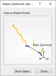
In the Helper, you can move and zoom in the object type. Click again the same input and the object type moves back to its initial position.
To close the Helper, click
 or Close or
 -
If the cross section has not been selected, click Sketch
 to
create a new sketcher-based typical cross section.
The Typical Cross Section Sketcher opens, allowing you to create the excavation profile and filling profile.
to
create a new sketcher-based typical cross section.
The Typical Cross Section Sketcher opens, allowing you to create the excavation profile and filling profile. -
To display or edit the typical cross section constraints in the 3D area, click
 .
Note: You can edit the dimensions of these constraints in the Constraint Definition dialog box directly in the Civil Engineering 3D Design.
.
Note: You can edit the dimensions of these constraints in the Constraint Definition dialog box directly in the Civil Engineering 3D Design. -
To swap the left profile with the right profile of the cross section when the profile
is not symmetrical, click
 .
.
This command is available only if the cross section is based on an alignment sketch.
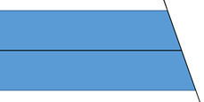
For a nonsymmetrical typical cross section, as shown in the left figure below, the default result does not always correspond to your expectation.
With this option you can swap the left and right profiles, as shown in the middle and right figures below:
-
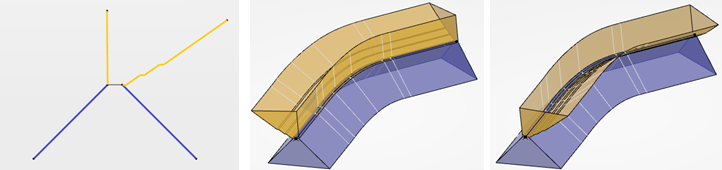
To extrapolate the last section of the cross section profile to the terrain, select
the Extrapolate cross section to terrain option in the
Parameters section of the dialog box. By default, this option
is selected.
- The cross section profile is systematically extrapolated to the terrain, as shown in the right figure below.
- To keep the profile as it is (as shown in the left figure below), without
extrapolation, clear the option.
 : Right side profile
without extrapolation.
: Right side profile
without extrapolation.  : Right side profile
with extrapolation.
: Right side profile
with extrapolation.
-
To edit sections, do the following:
- Set parameters on sections in the Sections area of the window. By default, there is a start and end section. Each section must have the same number of edges and vertices along the swept volume.
- Select the contextual command to display or hide parameters on a section in the 3D area.
-
Add a new section by clicking
 and selecting a point
on alignment for example. The new section inherits the previous section's
parameters. When you have three sections, additional contextual commands are
available: Remove and Order sections along the
alignment.
and selecting a point
on alignment for example. The new section inherits the previous section's
parameters. When you have three sections, additional contextual commands are
available: Remove and Order sections along the
alignment.
-
Select a destination stretch set to aggregate the newly created road or railway
stretch.
Notes:
- When a linear stretch or a stretch set have been set as current, you can select it in the Destination Set box.
- If the stretch set has already been aggregated, you cannot change its destination.
- When no terrain is selected, by default no stretch set is selected, and the stretch is created directly under the road or railway node.
- If you want to select an existing stretch set into which the current stretch is to be aggregated, first click the “Stretch Set”, then select the stretch set either in the 3D area or in the tree.
- Click
 to create a new road or
railway stretch set, and it is aggregated under the Stretch
Set in the tree.
to create a new road or
railway stretch set, and it is aggregated under the Stretch
Set in the tree. - Click to remove the selected
road or railway stretch set, and the current stretch is created out of any stretch
set.
- If an existing stretch set or a new stretch set is selected, the following
options are selected by default to create a modified terrain and, excavation and
filling works in the Stretch Set automatically:
- Create modified terrain: if you clear this option, the modified terrain is not created in the Stretch Set. When you select the option, the boundary of excavations and fillings is generated in the tree. If you click the boundary feature in the tree, it is highlighted in the 3D area.
- Create excavation and filling works: the excavation and filling works are also not created in the Stretch Set.
-
If a stretch has been aggregated into a stretch set, you cannot move it outside of the stretch set or into another stretch set.
- Optional:
To modify the terrain and compute excavation or filling works, select the following
options:
- If the terrain has not been selected, or if the terrain is selected but no Destination Set has been selected, only a road, railway, or platform stretch is created, without any modification of the terrain.
- If the terrain and the Destination Set have been
selected:
- If the Destination Set does not exist, then a new stretch set is created.
- Otherwise, the road, railway, or platform stretch is moved to the existing Destination Set.
- If the option Create modified terrain is not
selected, the terrain is modified. If not, it is deactivated. By default, the
with excavations and fillings option is selected and
you can see these modifications encrusted on the terrain:
- To modify the terrain and take only earthwork excavation stretches into account in terrain modification, click with excavations: filling stretches are ignored. To modify the terrain and take only earthwork filling stretches into account in terrain modification, click with fillings: excavation stretches are ignored and consequently excavation works are not computed.
- To remove the excavations and fillings from the modified terrain, select the
without excavations and fillings option:
- If you click with only excavations and fillings, the
modified terrain contains only excavations and fillings:
- If the option Create excavation and filling works is
selected, they are created, or modified if they have already been
created:

If not, they are deactivated.
- If the Create modified terrain option is selected, the
boundary of excavations and fillings is generated under the Stretch
Set in the tree. If you select the boundary in the tree, it is highlighted in the 3D area:
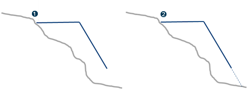
- To keep or remove the excavation or filling works, which are not connected to
the road, railway, or platform surface, select the Keep non-connected
excavation and filling works option. When a zone seems to be
meaningless for the surface (Zone2 in the example below), you can disconnect it
from the road, railway, or platform:
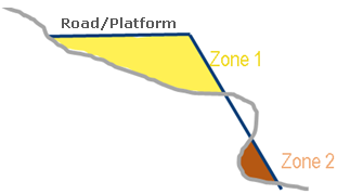
With this option, Zone2 is excluded from the filling works result.
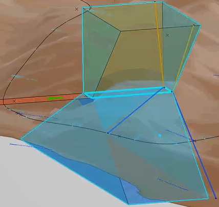
-
To visualize the impacts on and under the terrain, click
Preview.
With Preview, all UDF-based cross sections, used in the stretch computation, are displayed.
The preview displays the cross section in the shape of a sweep along the alignment:

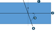
 Angle
between 0 degrees and 180 degrees (excluded). If it is equal to 90
degrees, no split is done at the extremities.
Angle
between 0 degrees and 180 degrees (excluded). If it is equal to 90
degrees, no split is done at the extremities. Plane
Plane