Introduction | ||
| ||
Problem Description
A heat exchanger is a mechanical system that allows heat to transfer between two or more fluids efficiently. Typically, a solid barrier with high thermal conductivity, such as a copper tube, separates these fluids.
Heat exchangers are classified by the arrangement of their fluid flows. In parallel flow heat
exchangers (shown below on the left), the fluids enter the heat exchanger at the
same end, and heat transfers between the fluids as they flow side by side through
the system. In counterflow heat exchangers (shown below in the middle), the fluids
enter the heat exchanger at opposite ends, and heat transfers between the fluids as
they pass by each other. In crossflow heat exchangers (shown below on the right),
the fluids travel roughly perpendicular to each other, and heat transfers between
the fluids as they flow through the system. In this example, you simulate the
efficiency of a shell-and-tube design, which is a type of crossflow heat
exchanger.
In a shell-and-tube heat exchanger (shown below), two fluids (one "hot" and one "cold") exchange heat within an enclosed shell, but the fluids never interact with each other. To facilitate heat exchange, you secure one end of the heat exchanger to a system that expels a hot fluid. The hot air flows through a bundle of tubes that run the length of the heat exchanger. At the same time, you pump a cold fluid through the heat exchanger's inlet nozzle. As the cold fluid travels through the heat exchanger, the baffles redirect the flow around the bundle of tubes in a spiral-like pattern (nearly perpendicular to the tubes at all times). This particular flow pattern facilitates efficient heat transfer between the two fluids. At the end of the baffle, there is an outlet nozzle for the cold fluid to exit the heat exchanger. The cold fluid always exits the heat exchanger warmer than it entered the heat exchanger.

![]() Shell
Shell
![]() Cap
Cap
![]() Tube
Tube
![]() Baffle
Baffle
![]() Inlet nozzle
Inlet nozzle
![]() Outlet
nozzle
Outlet
nozzle
This example is a simplified heat exchanger simulation in that you apply a constant surface temperature to the bundle of tubes. Therefore, there is no need to model the flow of a hot fluid through the bundle of tubes. In addition, water serves as the cold fluid.
You can measure the efficiency of a heat exchanger by the amount of thermal energy transferred between fluid masses over a set period of time. In this example, you evaluate the temperature difference in the water at the inlet nozzle versus the outlet nozzle during steady-state conditions.
Workflow
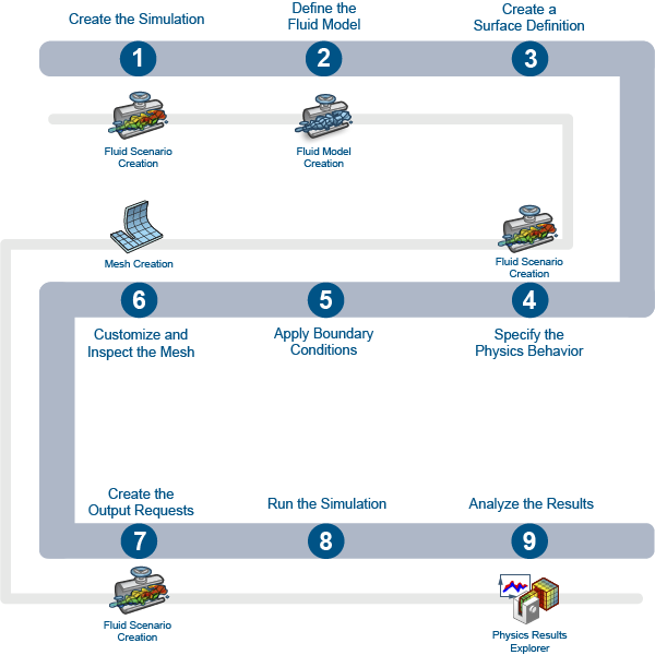
The workflow diagram below provides an overview of the example. The diagram shows the apps that you use as you perform the steps in sequence. Clicking a number in the diagram opens its corresponding step in the example.

| Task | Description | |
|---|---|---|
| 1 | Create the Simulation | Create the simulation by first importing the model and the material definitions into the 3DEXPERIENCE platform and then opening the model in the appropriate app. |
| 2 | Define the Fluid Model | Create the fluid domain, apply a material to it, and define the region where the flow occurs. |
| 3 | Create a Surface Definition | Group the outer surfaces of all the tubes into a single surface definition. |
| 4 | Specify the Physics Behavior | Specify the physics behavior of the water flowing through the heat exchanger. |
| 5 | Apply Boundary Conditions | Apply boundary conditions, such as flow conditions and wall temperatures, to the fluid domain. |
| 6 | Customize and Inspect the Mesh | Customize the mesh that you created when you defined the fluid domain, and inspect its quality. |
| 7 | Create the Output Requests | Create output requests to generate the fluid pressure, mass flow, and temperature results. |
| 8 | Run the Simulation | Verify that the steps for preparing the model, scenario, and mesh are complete. Then, run the simulation, and view the simulation status plots. |
| 9 | Analyze the Results | Generate, review, and interpret plots to understand the effects of the heat exchanger's design on its ability to exchange heat between fluids. |
Complete the workflow steps in the order in which they are listed. Deviation from the instructions associated with each step might cause model or scenario errors, which might prevent convergence of the simulation.