What's New | ||
| ||
R2022x FD01 (FP.2205)
- You can now add links to criteria files, better control mesh patterns, optimize surface elements, use enhanced trap selectors, and control mesh patterns in transition areas.
- The following features enhance meshing usability:
- Linked FEM and criteria file: Structural Model Creation now adds a link between the FEM and the criteria file in the database. When you run a quality analysis in Mesh Creation, you can now verify the current criteria set differs from the linked criteria and optionally synchronize the two files.
- Perforating and surface traps: The manual group command now
includes perforating and surface trap selectors. You can now select every node,
face, or element inside or a trap, or only those that are both inside the trap and
visible. The following figure shows a perforating trap:
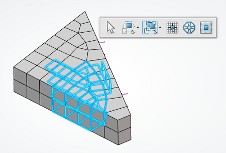
The performance of perforating traps is better than surface traps. - Rectangular traps for the surface mesher:
- Remesh Area: The Remesh area command now has two rectangular trap selectors (including and intersecting).
- Selection by neighborhood: The Remesh area command now has an option to enter the number of element layers. This eliminates the need to propagate selections layer by layer.
- Optimize surface elements for the surface mesher:
- Optimize Surface Elements: The Optimize Surface Elements command now has two rectangular trap selectors (including and intersecting).
- Selection by neighborhood: The Optimize Surface Elements command now has an option to enter the number of element layers. This eliminates the need to propagate selections layer by layer.
- Domain Selection enhancements: The Optimize Surface Elements command now has an improved domain selector that enables you to select more than one domain before validating the selection and beginning the optimization. In this manner, it optimizes the elements between the selected domains.
- Mesh transition pattern control: You can now better control the mesh pattern in transition areas. You can scan the mesh for rotating quad patterns in a surface quadrangle mesh. Rotating quads are elements in the same mesh domain with nodes connected to three or five elements.
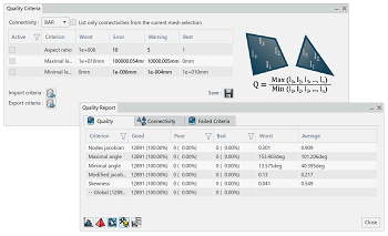
- The following enhancements make it easier to access mesh quality analysis information within the Quality Report:
- The Quality Criteria editor now opens by default when
running the Quality Analysis command for the first
time.
The Quality Criteria editor opens every time if it was docked to the Quality Report dialog when closed. - You can also access the Quality Report from a new context menu in the Mesh Part Manager. The Statistics Curves, Worst Elements Browser, Criteria Editor, and Create CSV File subpanels in the Quality Report are docked by default the first time they are opened.
- Display the current criteria file.
Important: If you previously edited the quality criteria for imported criteria, such as Elfini Checks, the Quality Report now prompts you to synchronize the current FEM with the initialization criteria stored in the database. - Display the total number of elements in the Global criterion.
- Display the worst elements in the model colored by quality. Mesh Creation highlights good elements in green, poor elements in yellow, and bad elements in red.
- Display the worst element for specific criteria. For example, you can display the worst elements for skewness.
- Reframe your view to specific elements in the Quality Detailed Report.
- Display the number of analyzed meshes and the number of mesh parts used in the quality analysis.
- List only the connectivities from the current mesh selection.
- The Quality Criteria editor now opens by default when
running the Quality Analysis command for the first
time.
- The Tetrahedron Mesher and Surface Mesher have enhanced capabilities.
- The Partition Hex Mesher now uses a structured meshing technique to fill rectangular volumes.
- The enhanced visualization management tool, the Visibility Manager, displays new options for finite element models and uses a more efficient selection method than in previous releases.
-
The Visibility Manager displays visualization options as action icons, as opposed to the lists used in previous releases. In addition, an information label
 helps you keep track
of the current action. For example, in the image below, the nodes and elements of the
excavator model are hidden:
helps you keep track
of the current action. For example, in the image below, the nodes and elements of the
excavator model are hidden: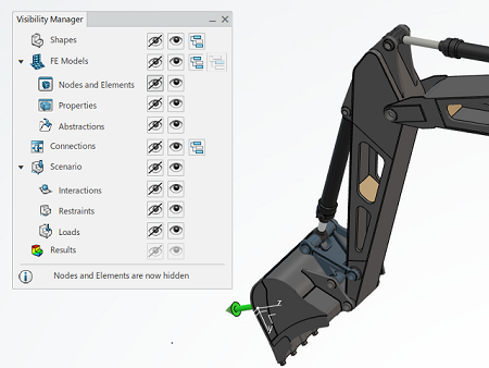
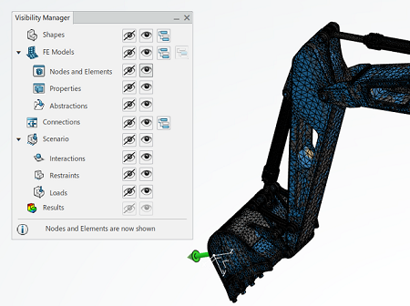
However, in the following image, the Visibility Manager settings display the nodes and elements of the excavator:
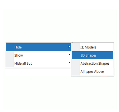
There have also been enhancements to the display of context menus. The context menus now show previously used commands when the Visibility Manager command is active.
The following image shows the context menu choices when the selected object is a FEM:
Mesh Usability Enhancements
Mesh Quality Analysis Enhancements
Tetrahedron Mesh and Surface Mesh Improvements
Structured Meshing Support for the Partition Hex Mesher
Enhanced Visualization Management
R2022x GA
- You can now run structural simulations on polyhedral geometry.
- Model and mesh capabilities are now contained within the model creation apps.
- The Lock Domain command is now enhanced and renamed Element Lock.