What's New | ||
| ||
R2022x FD01 (FP.2205)
R2022x GA
- A new command, Structure Resources Manager
 ,
lets you load the structure resources specified in Data Setup, in the active session.
 - You can now break panels and plates, using the new Break
Panel/Plate
 command.
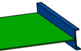
 - For the stiffeners on free edges placed on the boundaries of a panel, you can now specify the default flange orientation with respect to the panel.
- You can now select a face of a flange, as a limit for the parametric plate.
- The new Trim options now let you create a flange on the edge of a plate without increasing the overall length of the plate.
- Consistency is maintained between Structure Functional Design and Structure Design models, in drawings for example.
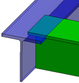
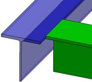
- Flanges can be in contact with other structural elements, for example they can be used as limits for other structural elements. When a Structure Functional Design model is synchronized with Structure Design, you can now avoid clashes.
- When you regenerate structure plates (exposed split plates) with the Geometry preference specified as Yes, the existing Declared Characteristics and Declared Weight extensions, if any, are now removed.
- You can now specify the attributes to compare between structure plates (exposed split plates) and their corresponding split plates.
- You now have better control over the update of exposed split plates.
- Unnecessary revisions of unaffected split plates in design reports are avoided.
- A new limit type, Short Weld, is now available. This limit type takes into account the first contact point between a limited profile and a limiting profile.
- The
V_StrSection_Standard,V_StrSection_Shape, andV_StrSection_Sizeattributes now replace theV_StrSectionattribute on the following structure types:Structure_Stiffener,Structure_StiffenerOnFreeEdge,Structure_Member,StrStiffener,StrStiffenerOnFreeEdge, andStrMember. - For the member objects created without a skeleton representation, the Qto parameters are now valuated automatically. You do not need to create any relations on them.
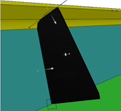
- New contour types, Snipe and Clearance, are now available for creating scallops.
- The scallops on the corners of a plate that is not perpendicular to the limiting panel are now created accurately.
- You can now create scallops on profiles. For more information, see Creating Scallops on Profiles
- The synchronization process precisely creates detail end cuts on Structure Design profiles, using the corresponding Structure Functional Design end cuts created using powercopy volume-based end cut references.
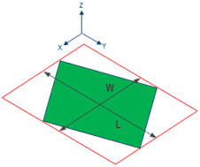
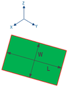
- The length and width of a panel, plate, or split plate are now computed optimally, when its orientation is different from that of the global axis system.
- The user interface was improved to guide you while creating structure objects and also restrain you from creating invalid objects.
- The Structure Fastener
 command adopts the new data model for fasteners.
 - A new command, xFrame PLM Exposition
 , lets
you generate Structure Design objects from xFrame objects.
 - You can now quickly perform various operations and create detail features using the short commands available on context toolbars.
- You can perform parametric design study on the Structure Design model, to test a number of design variations for potential evolution of an existing design.
Loading Structure Resources in Active Session
Benefits: Loaded resources ensure faster performance of the commands that use
them.
For more information, see
Using Structure Resources Manager
Breaking Panels and Plates
Benefits: After synchronizing your structure model to Structure Design, if need be, you can break panels and plates in Structure Design itself.
For more information, see
Breaking Panels and Plates
Default Section Orientation for Stiffeners on Free Edges
Benefits: The flange orientation is now computed with respect to the panel. The outward
flange orientation ensures that no stiffeners on free edges clash with the
panel.
Selecting Flange as a Limit for Parametric Panel
Benefits: You can stiffen a panel effectively by creating a bracket between a flange and
the panel.
For more information, see
Limits
Trim Options for Flange
Benefits:
For more information, see
Creating a Flange
Weight Management of Exposed Split Plates
Benefits: Efficiency is improved in weight calculation, as you can now compute the
weight of all structure plates (exposed split plates) in one go.
Updating Exposed Split Plates
Benefits:
For more information, see
Creating Plates from Split Plate Features
New Limit Type: Short Weld
Benefits: Clashes between limiting and limited profiles are avoided.
For more information, see
About Profile Limits
Enhanced Metadata Types
Benefits: The new attributes provide precise information on the section of
profiles.
Building & Civil Structure Object Type Enhancements
Benefits: The automatic valuation of the Qto parameters improves the user
experience.
Scallops: New Contour Types
Benefits: You now have increased openness in creating scallops.
Maintaining Effective Area of Scallops on Inclined Plates
Benefits: The scallops on inclined plates now provide maximum effective opening
area.
Creating Scallops on Profiles
Synchronizing with PowerCopy Volume-based End Cuts
Benefits: You can now create end cuts with higher accuracy and productivity in Structure Functional Design and synchronize them in Structure Design.
EKL for Structure Design
Benefits: Exact dimensions of plates are computed when the orientation of the plates is
different from the orientation of the global axis system.
User Experience Improvement
Benefits: The creation of invalid objects is no longer possible, which improves the user
experience.
New Fastener Data Model
Benefits: Bundles capture your design intent earlier in the process, and largely
optimizes the scalability and performance of the app.
For more information, see Fastening User's Guide.
Generating Structure Design from xFrame Objects
Benefits: You can use your model with Structure Design PLM objects for further processes such as detailing, BOM generation, manufacturing,
etc.
For more information, see
Generating Structure Design Objects from xFrame Objects
Availability of Short Contextual Commands
Benefits: You can now create detail features with higher productivity.
Performing Parametric Design Study
Benefits: You can explore a large number of design options by variation in
parameters.
For more information, see
Performing Parametric Design Study on Structure Design Model
- Collaborative Lifecycle: Creating Revisions in the Primary and Secondary Revision Format
- Administrators can now activate a primary and secondary revision format. This format activates a secondary ID, that is incremented every time you create a revision of a non-released object. The primary ID is incremented every time you create a revision of a released object.Benefits: The primary and secondary revision format enables you to differentiate major changes (identified by the primary ID) from design iterations (identified by the secondary ID).
For more information, see Collaborative Lifecycle User's Guide: Creating Revisions and Branches: About Revision Formats.
- 3DEXPERIENCE Native Apps Content Reference Guide
- To help you find the reference information you need to use the content delivered along with your app, you can consult the 3DEXPERIENCE Native Apps Content Reference Guide. For more information, see 3DEXPERIENCE Native Apps Content.
