Introduction | ||
| ||
Problem Description
This example illustrates the simulation process for manufacturing a T-shaped structure using a powder bed fusion build. A sequential thermomechanical analysis is performed, and residual stresses and distortions are measured.
The model is an assembly with a predefined scan path that was generated in the Powder Bed Fabrication app. The assembly consists of a build tray and a bridge structure, which includes a T-shaped printed part and supports. The build tray is a 280 mm × 280 mm × 50 mm rigid plate, which facilitates printing the T-shaped part and the supports. The printed part (T-shaped part) is 85 mm long, 20 mm thick, and 20 mm high. The printed part is a titanium alloy (TI6Al4V2) with a density of 4430 kg/m³, isotropic Young's modulus, thermal expansion coefficient, and thermal conductivity that are thermal dependent.

 Printed Part
 Supports
 Build Tray
The simulation is defined with a series of thermomechanical steps:
- A transient heat transfer step to predict the part temperature during the build.
- A static structural step to predict the residual stress caused due to the elevated temperatures.
- A static structural step to predict the post-annealing stresses on the printed part along with the supports and the build tray.
- A static structural step to simulate the removal of the build tray.
- A static structural step to simulate the removal of the printed supports and to evaluate the final residual stress and distortion caused to the printed part.
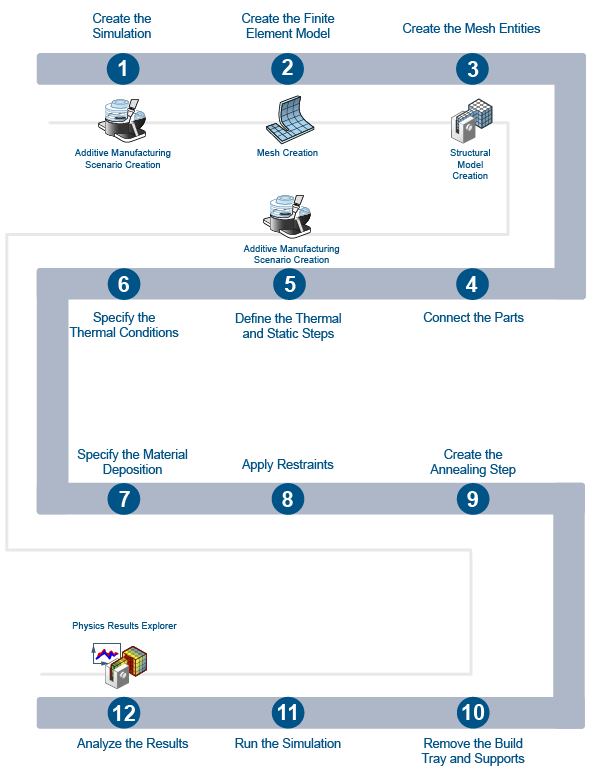
Workflow
The workflow diagram below provides an overview of the example. The diagram shows the apps that you use as you perform the steps in sequence. Clicking a number in the diagram opens its corresponding step in the example.
| Task | Description | |
|---|---|---|
| 1 | Create the Simulation | Create the simulation by first importing the model into the 3DEXPERIENCE platform and then opening the model in the appropriate app. |
| 2 | Create the Finite Element Model | Use a finite element model (FEM) representation of the assembly to perform the simulation and create groups for mesh entities. |
| 3 | Create the Mesh Entities | Use manual and geometric groups to define the loads and restraints on the mesh entities. |
| 4 | Connect the Parts | Define the tie connection between the parts and review the sections and materials. |
| 5 | Define the Thermal and Static Steps | Define the thermal and static steps with the initial and maximum time increments. |
| 6 | Specify the Thermal Conditions | Specify the initial temperature of the part and build tray and heat transfer conditions. |
| 7 | Specify the Material Deposition | Specify the material deposition roller's energy. |
| 8 | Apply Restraints | Apply restraints to define the directions your model can and cannot move during the simulation. |
| 9 | Create the Annealing Step | Create a new step to specify the annealing process using an amplitude curve. |
| 10 | Remove the Build Tray and Supports | Create two new static steps to specify the process of removing the build tray and the supports. |
| 11 | Run the Simulation | Run the simulation to predict the thermal and structural characteristics of the printed part. |
| 12 | Review the Results | Review the von Mises stresses, temperatures, and displacements before and after annealing. |
Complete the workflow steps in the order in which they are listed. Deviation from the instructions associated with each step might cause model or scenario errors, which might prevent convergence of the simulation.