What's New | ||
| ||
R2022x FD01 (FP.2205)
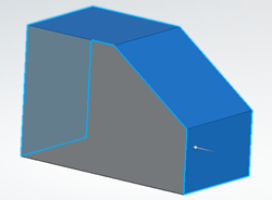
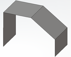
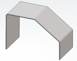
- The Hopper command now only lets you create canonic hoppers.
- To create a surfacic hopper, you must now create a free form surface using the Convert Surface.
- You can now collect technological information for sheet metal holes and threads that are present in a feature or a body.
- You can now select an ordered tool (tool body or ordered geometric set) as the input profile to create a cutout.
- You can now export sheet metal parts using the downward compatibility mode.
Canonic Hopper Command
Benefits: This method is also a new way to calculate the unfolded length of the
bend.
For more information, see
Creating Canonic Hoppers
Creation of a Surfacic Hopper with the Convert Surface Command
Benefits: The Convert Surface command provides the same
functionality as in the former Hopper command.
For more information, see
Creating Free Form Surfaces
Technological Results
Benefits: If you create a pattern of a feature, technological results are created
automatically for replicated instances. You can also create technological information
for pasted bodies. For more information, see Generating Technological Results.
Cutout Command
Benefits: Selecting an ordered tool eases the sheet metal design workflow.
Export Using Download Compatibility
Benefits: The 3dxml that contains the sheet metal parts is exported As
Result.
R2022x GA
- You can now use the bend allowance or bend deduction as methods for calculating the sheet metal unfolded length.
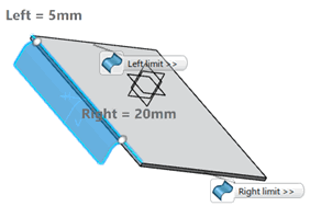
- When creating any kind of swept wall (flanges, hems, tear drops, and user flanges), you have more options when defining relimitations.
- You can now select the Optimize Geometry option when
creating standard cutouts
 or pocket cutouts
  .
. - You can now recognize surfaces and nonconstant thickness solids as sheet metal features. To do so, the Recognize dialog box now offers three recognition modes.
- You can no longer open dialog boxes with the legacy appearance.
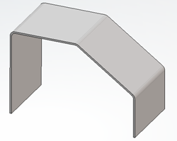
- When creating walls, tangent walls on edge, walls on edge with clearance, or sketch based tangent walls on edge, the results faces are now simplified, provided the input support faces are planar.
Ability to Calculate Unfolded Length Using Bend Allowance and Bend Deduction
Benefits: Previously, you could only use the K-factor as the method for calculating the
sheet metal unfolded length. You could use bend deduction only if it was defined through
the standards. Now, you can choose between the K-factor, bend allowance, bend deduction,
or in some cases, the bend deduction table defined in the standards (if
any).
Limiting Geometry Enhancements for All Swept Walls Commands
Benefits: Points, planes, or surfaces are no longer your only options to define the left
and right limits of the input spine. Furthermore, both limits are no longer mandatory.
This improves the user experience.
For more information, see
Relimitation
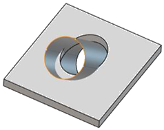
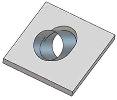
New Option for the Standard Cutout and Pocket Cutout
Benefits: Optimizing the geometry improves the result of the cutout or pocket, by taking
into consideration impacts on both the top and bottom faces.
For more information, see
Creating Cutouts
Recognize Command
Benefits: You can now recognize additional elements as sheet metal
features.
For more information, see
Recognizing Features
Removal of legacy appearance of dialog boxes
Benefits: You can now access only the dialog boxes with the new display.
Simplification of the Result when Creating a Wall or a Wall on Edge
Benefits: This capability eases the sheet metal design workflow.
