R2022x FD01 (FP.2205)
Property Manager
- You can now access an interactive list of properties, abstractions, and
behaviors that allows you to review, modify, and delete these items.
- The Property Manager lists these items for the active finite element model
(FEM) representation.
The Property Manager is particularly useful for large FEM
representations, because you can filter for specific features and organize the
parameters that you care about most into columns. You can access the Property
Manager from the Properties or
Abstractions section of the action bar.
Benefits: The Property Manager improves the usability of this app by
helping you edit properties, abstractions, and behaviors more efficiently than
before.
Ability to Store Relations in a Connection Template
- You can now store relations applied on connection parameters in a connection
template.
- When you create a connection of the same type, you can import the relations
that you previously stored in the connection template. The import creates the relations
for that connection in the active finite element model representation.
The app
supports the ability to store relations in a connection template for these features:
- Point fasteners
- Line fasteners
In addition, the app
supports the import of these connections for these features:
- Point fastener detection
- Line fastener detection
Benefits: The ability to store relations in a connection template improves your ability
to create multiple connections efficiently.
Full Coverage for Fluid Cavity Features
- You can now define the behavior of fluid cavities more effectively using an
expanded series of options that provide more flexibility and power.
-
When you define a material, you can now describe the material's pneumatic fluid
behavior (molecular weight and molar heat capacity). You can also use user subroutine
UFLUID to specify a
user-defined fluid cavity behavior. These material definition enhancements are
supported when you import an Abaqus input file (.inp) file that includes material data into the platform.
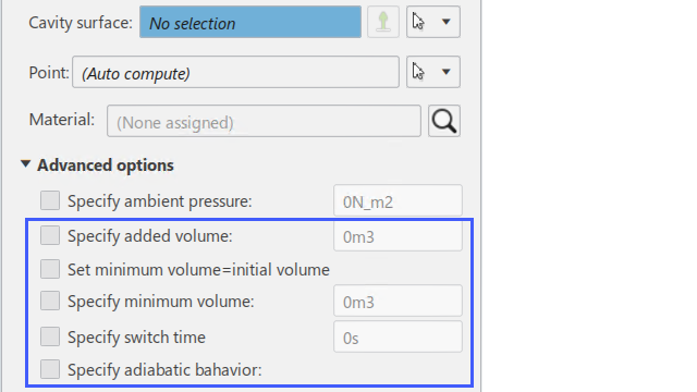
When you define a fluid cavity, you can now define the cavity's added volume, minimum
volume, switch time, and whether the fluid cavity exhibits adiabatic behavior.
When you define fluid exchange, you can now specify exchange behavior in terms of
energy flux; leakage of mass, volume, or energy; leakage through fabric or an orifice;
or a user-defined exchange behavior with user subroutines VUFLUIDEXCH and VUFLUIDEXCHEFFAREA.
Once your fluid cavity and fluid exchange definitions are complete, you can activate
fluid exchange for a simulation step in Mechanical Scenario Creation. You can also request history output for all fluid cavity–related output variables
that are supported for Abaqus analyses.
Benefits: The expanded options enable you to define fluid cavity behavior that is more
realistic and provides better simulation results.
For more information, see
Defining the Fluid Flow In and Out of Fluid Cavities
Improvements to Virtual Bolt Placement and Definition
- The functionality of virtual bolts has been expanded, allowing you to use
them in more kinds of models.
- You have new options for bolt placement, a new bolt construct for connecting
solid layers, and the influence radius display is more consistent.
When creating bolts
on shell geometry, you can now:
- Select noncircular holes as supports
- Select nonplanar holes as supports
When creating bolts on solid geometry, you can now:
- Use new beam element construct to model bolt behavior through solid layers
- Use option to ignore small chamfer faces at hole openings
When using virtual bolt detection, you can now:
- Detect bolt locations between shell layers and solid layers
- Detect bolts on noncircular holes (shells only)
Benefits: You can create virtual bolts on more types of geometry and use expanded
constructs to define their behavior.
For more information, see
Defining Virtual Bolts
Detecting Virtual Bolt Locations and Applying Virtual Bolts
Enhanced Connection Behaviors
- Improvements to connectors options give you access to advanced behaviors,
which are supported in connector templates and Abaqus input file import.
- Additional connector behavior options let you define:
- Connector failure
- Connector friction
- Multiple behavior definitions for the same behavior type
- Frequency-dependent data for elasticity and damping
- Advanced behaviors for connectors with springs
In addition you can take advantage of these new capabilities:
- Abaqus input file import supports advanced behaviors and derived components
- Connector templates now support advanced behaviors when saving or reusing a
template
Benefits: Connectors now have additional advanced behaviors allowing you to design more
realistic models.
For more information, see
Defining Connection Elasticity
Defining Connection Plasticity
Defining Connection Damping
Automatic Point Fastener Creation on Flanges
- You can now have point fasteners created automatically on part
flanges.
- You specify the flange geometry, and the app creates point fasteners along the
medial axis of the selection. You define the number of fasteners directly or by
specifying the spacing between fasteners.
Benefits: You can save time when creating fasteners on flanges because you do not need
to create additional geometric entities to define the fastener locations.
For more information, see
Defining Point Fasteners
Using Engineering Rules to Define Fastener Dimensions
- You can now define engineering rules that set connection parameters
automatically according to the thickness of the connected layers.
-
You create engineering rules that define relationships between connection parameters
and the layers that are connected. For example, you can define a spot weld diameter as
a function of one or more of the fastened layers.
You can use engineering rules to define:
- Spot weld diameters and cross sections
- Seam weld joint offsets, weld penetration, and weld fillet thickness.
Benefits: Engineering rules can make fastener creation more efficient by automatically
setting fastener parameters based on the model.
For more information, see
About Rule-Based Fasteners
Defining Rule-Based Fasteners
Usability Improvements for Point and Line Fasteners
- You can benefit from additional usability improvements when creating point
and line fasteners.
-
When you create fasteners, you now have the option to have them created as child
elements of the current FEM, instead of product-level engineering connections.
Previously, this option was available only when using the automatic fastener detection
tools.
The point fastener and line fastener dialog boxes are now more responsive to user
actions, and resize appropriately when you expand or collapse sections of the dialog
box.
Benefits: Fastener creation and fastener detection options are more consistent, and more
responsive dialog boxes minimize obstructions to the model view.
For more information, see
Defining Line Fasteners
Defining Point Fasteners
Specifying the Nodes to Restrain when Using Kinematic Coupling-to-Point
Connectors
- You now have more control over how the coupling restrains relative motions
between the connected nodes.
- When you release a degree of freedom from a kinematic coupling, you can
specify whether this release applies to the reference point or to the coupled
nodes.
Benefits: The ability to control how kinematic point couplings restrain the relative
motions between nodes gives you more flexibility and allows you to use the couplings in
a manner consistent with some legacy models.
For more information, see
Coupling Options
Viewing Fastener Configurations and Status Using Color Coding
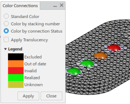
- You can now add color coding to point fasteners so that you can review the
fastener connectivity and status directly in the display.
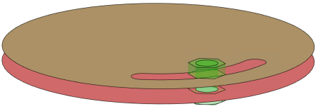
- You can use the coloring to visually inspect the number of connected layers
for each fastener or to see the fastener status (for example, fasteners that need
updates). In addition, you can make the model geometry and mesh temporarily translucent
so that the fasteners are easier to see.
Benefits: Color coding helps you quickly check the fastener definitions and locate any
fasteners that need corrections and updates.
For more information, see
Visualizing Connection Properties and Statuses by Color
New Icon Overlays for Finite Element Model Types in the Tree
- You can now identify certain types of FEMs by their appearance in the tree.
- In the tree, certain FEM types are displayed with icon overlays (also called tree masks) that
indicate the type of FEM. These types are identified:
- Axisymmetric
- Surrogate (substructure)
- Preloaded
- Imported
Benefits: Icons masks make it possible to quickly distinguish FEM types in the tree.
For more information, see
Tree Masks
Checking the Mesh Pattern in Transitional Areas
- You can now rapidly identify all areas throughout the mesh where patterns of
rotating quad elements occur.
-
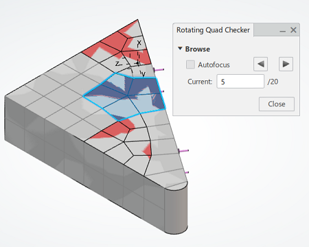
Rotating quads are places in the mesh where three or five quads connect to a single
node in the transition range. These rotating quads often occur as a result of the
default enabled Minimize triangles in transitions option. While
triangle meshes are superior to quad meshes for smooth transitions, a mesh composed of
quad elements is susceptible to rotating quads. Rotating quads are distorted quads
that might disturb energy transfer in the simulation.
You can use the Rotating Quad Checker to find all instances of
rotating quads in your mesh.
Benefits: You can locate rotating quad patterns to evaluate the quality of your mesh.
While quad meshes are better for structural simulations, they contain rough transitions.
Smoother transitions with more triangles create a better mesh pattern for Explicit
Dynamics analyses.
For more information, see
Identifying Rotating Quads in the Mesh Pattern
Mesh Navigation and Usability
- You can now directly access the mesh editing tools.
-
When you edit the mesh from Structural Model Creation, the app enters the appropriate editing workbench and opens mesh edit commands such
as Optimize, Remesh, and
Manual Edit. These commands are also now available in all
workbenches when clicking on other mesh parts as well as when switching to mesh
editing.
The context toolbar is now available for meshes of assembled FEMs. You can also use the context toolbar to navigate between meshes during editing.
The Worst Element Browser has been renamed the
Element Browser and has enhanced functionality. The element
browser allows you to browse worst elements, single elements selected in the 3D area,
or bad elements selected in the table.
In addition, three element visualization modes are now available:
- Show all: displays all elements in the mesh.
- Show all element: displays all browsed elements.
- Show current element: displays the currently selected
element and specified neighboring layers.
Benefits: Structural Model Creation users can now access quality analysis without switching apps. These context toolbar shortcuts allow you to switch between meshparts for editing without having to leave
the workbench to edit a different one. This applies not only in the current active FEM,
but also to meshparts that are in the FEM assembly.
For more information, see
Viewing Individual Elements by Quality Criteria
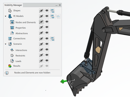
Enhanced Visualization Management
- The enhanced visualization management tool, the Visibility
Manager, displays new options for finite element models and uses a more
efficient selection method than in previous releases.
-
The Visibility Manager displays visualization options as action
icons, as opposed to the lists used in previous releases. In addition, an information
label helps you keep track of the current action. For example, in the image below, the
nodes and elements of the excavator model are hidden:
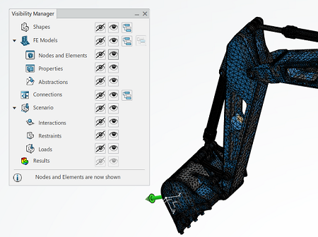
However, in the following image, the Visibility Manager settings
display the nodes and elements of the excavator:
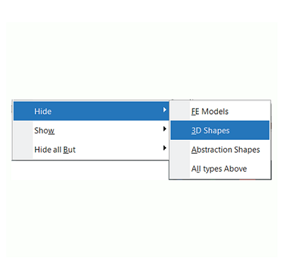
There have also been enhancements to the display of context menu. The context menu now show revisited entries when the Visibility Manager command
is active. The following image shows the context menu choices when the selected object is a FEM:
Benefits: The modified Visibility Manager and the enhancements to
the associated context menus reduce the number of clicks you need to activate commonly used options.
For more information, see
Managing the Visualization of Simulation Entities
R2022x GA
Simulations with Polyhedral Geometry
- You can now run structural simulations on polyhedral geometry.
- Polyhedral geometry is a less strict representation of a 3D shape than
CAD-based geometry. It consists of many multifaceted shapes joined at their edges to
produce an overall object. You might have polyhedral geometry as the result of a
physical scan of terrain or living shapes or from running an optimization of a design
that began as a CAD shape.
You can use polyhedral geometry in place of CAD geometry in
all actions except fastener detection and octree meshes.
Benefits: You can map the simulation properties and loads from the simulation for a CAD
design to an updated, polyhedral version of the same design to verify that the new
design meets the original specifications.
Locking Elements and Domains
- The Lock Domain command has been enhanced and renamed
Element Lock.
-
You can now:
- Manually lock or unlock individual elements or all the elements of the selected
domain.
- Lock a closed mesh domain that you define from a subregion of the mesh.
Mesh Creation displays locked elements as translucent. In addition, locked elements and domains
remain locked across sessions.
Note:
Locking behavior occurs at the element level; you cannot specify nodes, edges,
or element faces.
Benefits: Locking individual elements or the elements of a selected domain allows you to
modify parts of the mesh while keeping the locked portions unchanged.
For more information, see
Splitting Quadrangles into Triangles
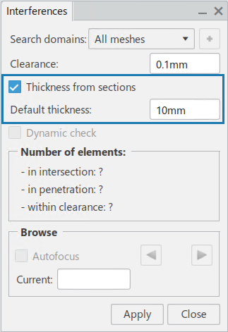
Mesh Interference
- When you check for interference, you can now account for the thickness of the
sections in your model.
- The app uses the actual section thickness, and you can add a default thickness
for any sections where the thickness is unknown. If there is mesh interference, you can
review the elements with different types of interference based on their coloring: red
for intersection, orange for penetration, and yellow for clearance.
Benefits: Adding section thickness to the interference checks accounts for the real
shape of the model, rather than checking the design which is typically at the center of
the thickness.
For more information, see
Checking Interferences
Model and Mesh Unification
- All actions for creating, editing, and reviewing the mesh and finite element
model for a simulation are now located in the Structural Model Creation and Fluid Model Creation apps.
- The action bar sections have been integrated and there is no longer a “switch
to mesh” function.

Benefits: You can now complete all mesh and finite element model creation and editing
actions within the model creation apps. This provides a seamless interaction with no
need to switch between apps to create the model and mesh features for your
simulations.
For more information, see
Mesh Section
Proxy and Source Selection Guidance for Functional Structure Finite Element
Models
- The user interface for the Functional Structure FEM
 option now
prevents you from making an invalid selection. option now
prevents you from making an invalid selection.
- When you create a functional structure finite element model (FEM), you must
select a proxy and a source from the product instantiating the FEM representation. If
you attempt to select the proxy or the source from an invalid location, the pointer
changes to
 and blocks your selection. and blocks your selection.
Benefits: The improved feedback mechanism improves the user experience for creating a
functional structure FEM.
For more information, see
Creating Functional Structure Finite Element Models
Composite Sections
- Improvements have been made to the procedure for associating composite layup
definitions with geometric or mesh parts.
-
These usability enhancements simplify the definition of composite sections as
follows:
- You can visualize the core sampling depth on the mesh, and you can use a new
interactive tool to edit the core sampling depth directly in the model
display.
- You can use the composite mapping algorithm with automatic offset options with
fewer restrictions:
- You are no longer required to have your mesh normal and composite surface
normal face opposite orientations.
- You can use ply groups that have different draping directions and rely on
the app to map to determine the correct offset and ply order.
Benefits: You have more control over the core sampling depth for composite sections and
fewer constraints on the orientation and draping directions.
For more information, see
Defining Composite Shell Sections
Defining Composite Continuum Shell Sections
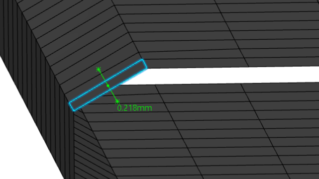
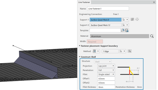
Meshing Lap Joints
- You can now use line fasteners to model welded lap joints when you use the
support boundary placement method.
- You define the penetration and fillet parameters in the fastener definition,
and the app automatically projects the required mesh restraints on the fastened parts.
Previously, the support boundary placement method only supported T joints.
Benefits: You can now use line fasteners to model welded lap joints
efficiently.
For more information, see
Defining Line Fasteners Using the Support Boundary Method
|