Introduction | ||
| ||
Problem Description
A new aircraft design requires a very high frequency (VHF) blade antenna positioned on its exterior surface to enable communication with radio control towers. The antenna, shown below, operates at 127.5 MHz and has good omnidirectional coverage in its uninstalled state. You define three potential installed positions for the antenna, and run simulations to evaluate and compare the installed antenna's performance.

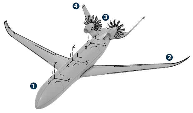
The aircraft is similar in design to those used by modern commercial airlines. For example, the skin of the aircraft is metal, which blocks most forms of electromagnetic radiation. The image shown below labels the aircraft's design features used throughout this example.

![]() Fuselage
Fuselage
![]() Wings
Wings
![]() Propellers
Propellers
![]() Tail
fins
Tail
fins
The cockpit is in the front of the aircraft, the passenger cabin is in the midsection, and the luggage compartment is in the rear. The three antenna positions you evaluate in this example are on the fuselage's exterior surface at the front, middle, and rear of the passenger cabin. You select these positions based on limitations from other aspects of the design. Your job is to determine which installed antenna has the best performance and if that installed antenna still has omnidirectional coverage.
Workflow
The workflow diagram below provides an overview of the example. The diagram shows the apps that you use as you perform the steps in sequence. Clicking a number in the diagram opens its corresponding step in the example.

| Task | Description | |
|---|---|---|
| 1 | Create the Simulation | Create the simulation by first saving your CST antenna project to the 3DEXPERIENCE platform and importing the model into the 3DEXPERIENCE platform, and then opening the model in the appropriate app. |
| 2 | Define the Model | Define your model by adding a platform and an antenna to the 3D area of your antenna placement simulation. |
| 3 | Define the Placement Candidates | Define placement candidates to designate potential locations for simulating the installed antenna. |
| 4 | Generate Obscuration Plots | Plot how the aircraft's geometry obscures the field of view of each placement candidate. |
| 5 | Create the Coverage Tests | Create coverage tests for each of the placement candidates that you plan to simulate |
| 6 | Request Additional Output | Request additional output parameters for your results analysis. |
| 7 | Configure the Master Simulation Project | Configure the master simulation project to optimize settings applied to the simulation. |
| 8 | Run the Simulation | Simulate the coverage tests to generate results for each installed antenna's performance. |
| 9 | Analyze the Results | Review the radiation patterns, key performance indicators, and 3D results of your simulations to evaluate each antenna's performance. |
Complete the workflow steps in the order listed. Deviation from the instructions associated with each step might cause model or scenario errors, which might prevent convergence of the simulation.