Introduction | ||
| ||
Problem Description
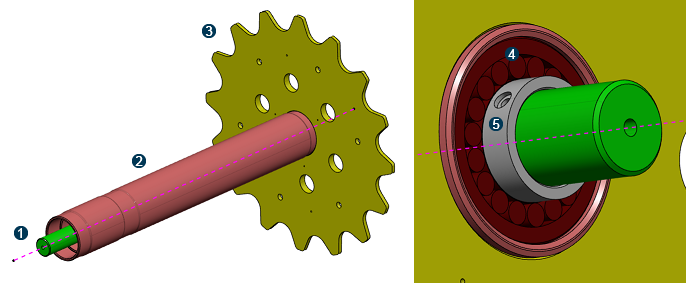
A driveshaft assembly consists of a hollow shaft with an attached sprocket (that is, a gear). The hollow shaft is coupled to a solid support shaft by a bearing at each end. The bearings allow the hollow shaft and sprocket to rotate around the support shaft. The model used in this example, shown below, has a bearing stopper at the sprocket end of the driveshaft. A distance washer (that is, a snap ring) fits inside the hollow shaft up against the bearing on the side opposite from the bearing stopper. The model is approximately 1.05 meters along the length of the shaft, and the sprocket is approximately 0.7 meters in diameter. The entire driveshaft assembly is made from a steel alloy.

![]() Support
shaft
Support
shaft
![]() Hollow shaft
Hollow shaft
![]() Sprocket
Sprocket
![]() Bearing
Bearing
![]() Bearing
stopper
Bearing
stopper
Typically, you run a global analysis, review the results, and determine regions that require a more detailed analysis before running a submodel analysis. To streamline this example, however, you create both the global and submodel analyses and run them simultaneously. The submodel analysis uses parameters from the global analysis but with a refined mesh size; therefore, the app runs the submodel analysis after the global analysis finishes.
In this scenario, you apply a rotational force to the sprocket to mimic the sprocket and hollow shaft rotating around the support shaft. You are most interested in the forces transmitted between the sprocket and the support shaft. Therefore, the sprocket end of the driveshaft assembly is your submodel for the refined analysis.
You define the submodel using an abstraction shape created near the sprocket end of the driveshaft. The abstraction shape, which is a plane, is shown below on the meshed model.

Workflow
The workflow diagram below provides an overview of the example. The diagram shows the apps that you use as you perform the steps in sequence. Clicking a number in the diagram opens its corresponding step in the example.

| Task | Description | |
|---|---|---|
| 1 | Import the Files | Import the model and the material definition into the 3DEXPERIENCE platform. |
| 2 | Create the Global Finite Element Model | Define the meshes for the global finite element model. |
| 3 | Define the Submodel | Define the submodel using an abstraction shape. |
| 4 | Create the Submodel Finite Element Model | Define the meshes for the submodel finite element model. |
| 5 | Apply a Material Definition | Apply a material definition to all of the parts in the driveshaft assembly to fully define the solid sections you previously created. |
| 6 | Create the Analysis Cases | Create the global and submodel analysis cases. |
| 7 | Define the Contact Interactions | Define contact between part surfaces to create and maintain the relationships between them. |
| 8 | Define the Loads and Restraints | Define the force that attempts to move the driveshaft assembly, and define the restraints that anchor the assembly. |
| 9 | Run the Simulation | Run the simulation to generate results for both the global and submodel analysis cases. |
| 10 | Analyze the Results | Analyze the results and determine if you are satisfied with the submodel analysis. |
Complete the workflow steps in the order in which they are listed. Deviation from the instructions associated with each step might cause model or scenario errors, which might prevent convergence of the simulation.