Introduction | ||
| ||
Problem Description
O-rings have many industrial applications where they act as seals to prevent the passage of gas or fluid from one space into another. In this example, you simulate sealing a cylindrical vacuum chamber, which is assembled with a top plate, an O-ring, and a bottom plate with a groove. You apply a force to the top plate to push the O-ring into the groove in the bottom plate. As the top plate pushes the O-ring into the groove, the O-ring flattens vertically but expands laterally, causing it to contact the groove walls. Since the assembly and the applied load are axisymmetric, you create a 1-degree cut-section of the assembly to reduce the analysis time of the simulation.
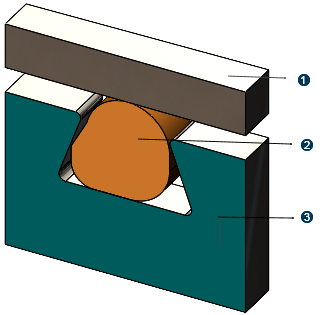
 Top plate
 O-ring
 Bottom plate with groove
The top and bottom plates are made of AISI-304 steel, while the O-ring is made of a custom rubber material. You use the Mooney-Rivlin model to represent the O-ring's hyperelastic material behavior.
The assembly and initial simulation setup were created in SOLIDWORKS. You save the assembly to the 3DEXPERIENCE platform and complete the simulation using 3DEXPERIENCE simulation apps.
Workflow
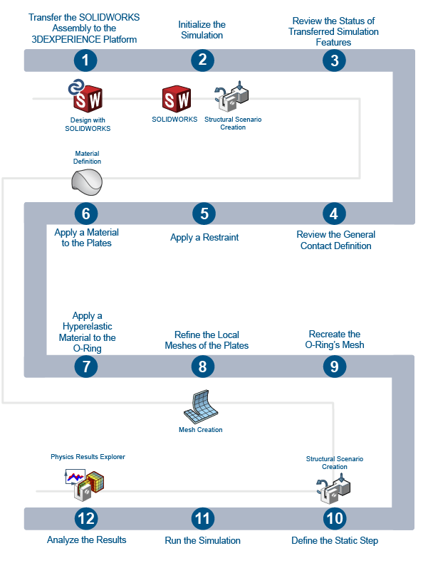
The workflow diagram below provides an overview of the example. The diagram shows the apps that you use as you perform the steps in sequence. Clicking a number in the diagram opens its corresponding step in the example.
| Task | Description | |
|---|---|---|
| 1 | Transfer the SOLIDWORKS Assembly to the 3DEXPERIENCE Platform | Open the O-ring assembly in SOLIDWORKS, and transfer it to the 3DEXPERIENCE platform. |
| 2 | Initialize the Simulation | Initialize a 3DEXPERIENCE structural simulation. |
| 3 | Review the Status of Transferred Simulation Features | Review the status of simulation features you transferred from SOLIDWORKS to the 3DEXPERIENCE platform. |
| 4 | Review the General Contact Definition | Review the contact property assigned to the general contact definition. |
| 5 | Apply a Restraint | Apply a restraint that prevents the lateral movement of the bottom and top plates during the simulation. |
| 6 | Apply a Material to the Plates | Apply the AISI 304 steel material definition to the bottom and top plates. |
| 7 | Apply a Hyperelastic Material to the O-Ring | Create a custom rubber material, and apply it to the O-ring. |
| 8 | Refine the Local Meshes of the Plates | Refine the mesh definitions at the regions of the bottom and top plates that contact the O-ring during the simulation. |
| 9 | Recreate the O-Ring's Mesh | Recreate the O-ring mesh using hybrid hexahedral ("brick") elements. |
| 10 | Define the Static Step | Define the static step properties of the structural analysis case. |
| 11 | Run the Simulation | Run the simulation to predict the O-ring's behavior as the top plate presses it into the groove. |
| 12 | Analyze the Results | Analyze the results of the simulation to determine the efficacy of the O-ring. |
Complete the workflow steps in the order in which they are listed. Deviation from the instructions associated with each step might cause model or scenario errors, which might prevent convergence of the simulation.